
Serial Gateway App
|
Version |
Changelog |
Date |
Download |
|---|---|---|---|
|
1.0.0 |
Initial release. RS-232 ↔ TCP gateway with server, client and combined modes; full Barionet 50 serial parameter set; disconnect timeout; buffer flush on connect; multi-client broadcast; TCP keepalive; syslog diagnostics |
2026-08-17 |
|
|
1.1.0 |
Added IP filtering (allowlist of single addresses and CIDR subnets) for Server mode |
2026-08-17 |
|
|
1.2.0 |
Added configuration validation layer: every setting is type-checked, range-clamped and logged; a corrupt or incomplete |
2026-08-17 |
|
|
1.2.1 |
Fixed logging |
|
Application Version: 1.2.1
Compatible Firmware: Flexa Firmware min. v2.3.4
Overview
The Serial Gateway Application turns the Barionet M44 into a transparent bridge between its
RS-232 interface and a TCP/IP network. Any device with a serial port — a PLC, a display
controller, a scale, a matrix switcher, a gate controller — becomes reachable over Ethernet
without changing its protocol: bytes arriving on a TCP connection are transmitted on the
serial port, and bytes received on the serial port are sent back over the TCP connection.
This is the M44 equivalent of the built-in Serial Gateway function of the Barionet 50, extended with an outbound Client mode, an IP allowlist, and multi-client operation.
Compatible Hardware
The Serial Gateway Application is designed for Barionet M44 devices running Flexa Firmware
v2.3.4 or later. It uses the built-in RS-232 interface, which is exposed to the operating
system as /dev/ttyS1. The M44 provides one user-accessible UART, so one gateway instance
runs per device.
The application does not use the relays, digital inputs or a UX8 extension module, so it can
be deployed on any M44 regardless of the I/O options fitted. Functionally it replaces the
serial gateway of the legacy Barionet 50 and Barionet 100; all serial parameters offered by
those models (speeds up to 230400 baud, 7 or 8 data bits, parity, stop bits, hardware and
software flow control) are supported.
Installation Process
Installing the application requires uploading the package zipped file directly to your Barionet device through its web interface. This process is straightforward but requires careful attention to ensure proper installation.
NOTE: If your Barionet M44 is already running an application you must RESET TO DEFAULTS before proceeding and installing a new one.
Step 1: Access the Device Web Interface
-
Open your web browser and navigate to your Barionet device's IP address
-
Enter your administrator username and password when prompted
-
Wait for the main interface to load completely before proceeding
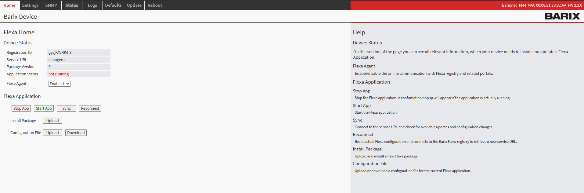
Barionet M44 User Interface
Step 2: Upload the Application Package
-
Navigate to the HOME tab in the main menu
-
Locate the "Upload" button next to “Install Package” within the page
-
Click the file selection button and browse to the “<package>.zip” which was downloaded from this page
-
Choose an appropriate version number for tracking purposes (this can be any number you prefer for identification)
-
Click the UPLOAD button to begin the installation process
Step 3: Device Reboot and Verification
After the upload completes, your Barionet device will automatically initiate a reboot sequence. This reboot is necessary to properly integrate the new application into the system. The reboot process typically takes 30..40s
-
Wait for the device to complete its reboot cycle
-
Reconnect to the web interface using the same IP address and credentials
-
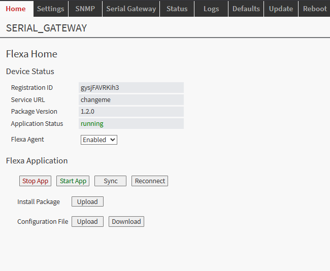
Navigate back to the HOME tab
-
Verify that the application status appears with a status of "running"
Configuration Overview
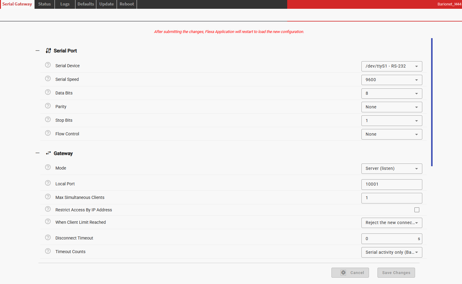
All settings are made in the SERIAL GATEWAY tab of the device web interface. The form is
divided into four sections: Serial Port, Gateway, Advanced and Logging.
NOTE: The application restarts automatically every time the configuration form is
submitted. Any open TCP connection is closed and the serial port is reopened with the new
parameters. There is no need to reboot the device.
Main Configuration Settings
The Serial Port section defines the physical line parameters. They must match the connected
equipment exactly; a mismatch produces garbled data rather than an error message.
|
Setting |
Options |
Default |
|---|---|---|
|
Serial Device |
|
|
|
Serial Speed |
300, 600, 1200, 2400, 4800, 9600, 19200, 38400, 57600, 76800, 115200, 230400 |
9600 |
|
Data Bits |
7, 8 |
8 |
|
Parity |
None, Even, Odd |
None |
|
Stop Bits |
1, 2 |
1 |
|
Flow Control |
None, Software (XON/XOFF), Hardware (RTS/CTS) |
None |
Flow Control behaves as on the Barionet 50:
-
None — no flow control.
-
Software (XON/XOFF) — transmission stops on XOFF (0x13) and resumes on XON (0x11).
Not suitable for binary data, because those byte values are consumed as control characters. -
Hardware (RTS/CTS) — data is only transmitted while CTS is asserted; RTS is dropped when
the receive buffer fills.
The Gateway section defines how the TCP connection is established:
-
Mode — Server (listen), Client (connect out), Server + Client, or Disabled.
-
Local Port (Server / Server + Client) — the TCP port the gateway listens on.
Default10001, as on the Barionet 50. Setting it to0disables the listener. -
Max Simultaneous Clients (Server / Server + Client) — 1 to 8, default
1, which
matches Barionet 50 behaviour. With more than one client, serial data is sent to every
connected client and data from any client is written to the serial port. -
When Client Limit Reached — Reject the new connection (default) or Replace the oldest
connection. The second option is useful when a stale half-open socket would otherwise
block the port until it times out. -
Remote Host / Remote TCP Port (Client / Server + Client) — the TCP server the
gateway connects to. Accepts an IP address or a hostname. -
Reconnect Interval (Client / Server + Client) — seconds between reconnection attempts.
Default10.
Access Control (IP Filtering)
Restrict Access By IP Address limits which hosts may open a connection to the gateway
port. When it is disabled, any host that can reach the device may connect.
When enabled, an Allowed Clients list appears. Each entry is either a single IP address
or a CIDR subnet; up to 16 entries can be defined:
-
192.168.1.50— one specific host -
192.168.1.0/24— an entire subnet -
10.0.0.0/8— a larger address block
Connections from any other address are closed immediately at accept time and recorded in the
log with the source address and port:
WARNING rejected connection from 192.168.2.6:63409 (not in allowed clients)
The active list is confirmed in the log at startup:
INFO IP filter active, allowed clients: 10.0.0.0/8, 192.168.2.99/32
NOTE: The filter fails closed. If it is enabled but the list is empty — or every entry
is invalid — all incoming connections are rejected and an error is written to the log at
startup. This is deliberate: a misconfigured filter must not silently leave the port open.
The filter applies to incoming connections only. It has no effect in Client mode, where the
gateway dials a host that is already explicitly configured.
NOTE: IP filtering is an access-control convenience, not a security boundary. Source
addresses can be spoofed on an untrusted network and the connection carries no encryption.
If the gateway port must be reachable beyond a trusted LAN, place it behind a VPN or an SSH
tunnel.
Connection Handling and Recovery
-
Disconnect Timeout — closes an idle incoming connection after the configured number of
seconds, 0 to 255, default0(never). This is the same function as the Barionet 50
Disconnect Timeout. It applies to incoming connections only; dropping the outbound Client
connection would simply trigger an immediate reconnect. -
Timeout Counts — selects what resets the timer: Serial activity only, which reproduces
the Barionet 50 definition, or Any traffic (serial or TCP). -
Flush Serial Buffers On Connect — discards stale serial data when the first connection is
established, so a new session starts on a clean line. Enabled by default. -
TCP Keepalive — detects and drops dead connections after 30 seconds of idle time using
3 probes 10 seconds apart. Enabled by default. Without it, a peer that vanishes without
closing its socket can hold a connection slot indefinitely.
In Client mode the gateway retries indefinitely: after a failed connect, a failed name
resolution, or a disconnect by the remote end, it waits Reconnect Interval seconds and tries
again. If the serial port reports an I/O error, it is closed and reopened automatically after
2 seconds; TCP connections stay up while this happens.
Advanced Settings
These settings tune buffering behaviour and rarely need to be changed.
|
Setting |
Range |
Default |
Purpose |
|---|---|---|---|
|
Max Packet Size |
64 – 8192 bytes |
1024 |
Largest block of serial data placed into a single TCP segment |
|
Packet Gather Time |
0 – 1000 ms |
0 |
Collects serial bytes for this long before sending them; |
|
Queue Limit |
1 – 1024 kB |
64 |
Per-direction buffer for a stalled peer or a flow-controlled serial port |
Packet Gather Time is worth raising to 10–50 ms for character-oriented devices, to avoid
one TCP packet per character, or to keep message frames (for example Modbus RTU telegrams)
together in a single segment.
Queue Limit protects the gateway when one side is much slower than the other — for example
a 1 MB burst arriving over Ethernet destined for a 300 baud port. When the buffer is full the
oldest data is discarded and a warning with a running dropped-byte count is logged. The
gateway keeps running; it never blocks or stalls the opposite direction.
Remote Logging Configuration
-
Enable Syslog — enabled by default.
-
Syslog Server — the collector as
IP:port, for example192.168.1.10:514. Leave empty
to log locally on the device. -
Log Level — Debug, Info (default), Warning or Error.
-
Statistics Interval — logs byte counters and the number of connected peers at this
interval, in seconds.0(default) disables periodic statistics.
Typical startup output:
INFO SERIAL_GATEWAY 1.2.0 starting, mode=server
INFO serial /dev/ttyS1 open: 115200 baud, 8N1, flow=none
INFO listening on TCP port 10001 (max 1 client(s), on limit: reject)
INFO inbound connection 192.168.2.6:52310 established (1 peer(s))
Connection establishment and closure, rejected connections, buffer overflows, serial errors
and configuration problems are all reported. Set the level to Debug when commissioning a new
installation.
Operational Behavior
Data Handling and Transparency
The gateway is fully byte-transparent. Data is never parsed, decoded, framed or escaped: the
full 0x00–0xFF range, including NUL bytes, control characters and invalid text encodings,
passes through unchanged in both directions. No protocol is imposed on top of the connection.
Two characteristics follow from the serial hardware itself rather than from the application:
-
In 7 data bits mode the UART strips the eighth bit, so 8-bit data is received masked to
the range 0x00–0x7F. Use 8 data bits for binary traffic. -
With Software (XON/XOFF) flow control, the byte values 0x11 and 0x13 in a binary stream
are consumed by the driver as flow-control characters. Use None or Hardware (RTS/CTS)
for binary traffic.
With multiple clients connected, data from any client is written to the serial port, and
data read from the serial port is sent to every connected client, including the client
that triggered the exchange.
Real-Time Operation
The application is event-driven: it sleeps until the serial port or a socket becomes ready,
then forwards immediately. With Packet Gather Time at its default of 0, serial data is
sent onward as soon as it is read, and Nagle's algorithm is disabled (TCP_NODELAY) so small
messages are not delayed by the TCP stack. Added latency is therefore dominated by the serial
line itself and by network round-trip time, not by the application.
The design is single-threaded and non-blocking in both directions. A slow or stalled TCP peer
cannot block the serial port, and a serial port held off by RTS/CTS or XON/XOFF cannot block
the network side; each direction buffers independently up to Queue Limit.
Serial Port Handling
The serial port is opened at startup with the configured parameters and held open for the
lifetime of the application, independently of whether any TCP connection exists. Data arriving
on the serial port while no client is connected is discarded rather than queued, which
prevents a stale backlog from being delivered to the next client that connects.
If the port cannot be opened at startup — wrong device path, or the port in use — the failure
is logged and retried every 2 seconds; the TCP side continues to operate meanwhile, so the
application remains reachable and reconfigurable.
Configuration values are validated on load. Each setting is checked against its type and
allowed range, out-of-range values are clamped, unrecognised values fall back to the factory
default, and every correction is written to the log. A config.json that is missing,
truncated or corrupt causes the application to start with default settings rather than fail
to start.
Configuration Examples
Basic Two-Device Setup
Two Barionet M44 units connect two serial devices across an IP network, back to back. One unit
listens, the other dials out; data flows in both directions regardless of which end initiated
the connection.
Device A — 192.168.1.10 (Server)
-
Mode:
Server (listen) -
Local Port:
10001 -
Max Simultaneous Clients:
1 -
Restrict Access By IP Address: enabled, Allowed Clients:
192.168.1.11 -
Serial Speed:
9600, Data Bits:8, Parity:None, Stop Bits:1, Flow Control:None
Device B — 192.168.1.11 (Client)
-
Mode:
Client (connect out) -
Remote Host:
192.168.1.10 -
Remote TCP Port:
10001 -
Reconnect Interval:
10 -
Serial Speed:
9600, Data Bits:8, Parity:None, Stop Bits:1, Flow Control:None
Both ends must use identical serial line settings to avoid data corruption. Device B restores
the link automatically if the network or Device A becomes unavailable.
Control Software Polling a Serial Device
A PC application or building-management system opens a TCP socket to the M44 and talks to the
attached serial device directly. This is the direct replacement for the Barionet 50 built-in
serial gateway.
-
Mode:
Server (listen) -
Local Port:
10001 -
Max Simultaneous Clients:
1 -
When Client Limit Reached:
Replace the oldest connection -
Disconnect Timeout:
60, Timeout Counts:Serial activity only -
Serial parameters as required by the attached device
Replace the oldest connection combined with a disconnect timeout ensures the port cannot be
left blocked by a control system that crashed without closing its socket.
Device Reporting to a Central Collector
An M44 installed behind a firewall or NAT router sends data from a serial instrument to a
central server. No inbound connection to the device is required.
-
Mode:
Client (connect out) -
Remote Host:
collector.example.com -
Remote TCP Port:
9000 -
Reconnect Interval:
30 -
TCP Keepalive: enabled
-
Packet Gather Time:
50ms -
Enable Syslog: enabled, Syslog Server:
192.168.1.10:514
Packet Gather Time groups character-by-character instrument output into complete lines
before transmission, reducing packet count over a WAN link.
Software Disclaimer
IMPORTANT:
This software application ("Software") is provided "AS IS" without warranty of any kind, express or implied, including but not limited to the warranties of merchantability, fitness for a particular purpose, and non-infringement. In no event shall the author, developer, or distributor be liable for any claim, damages, or other liability, whether in an action of contract, tort, or otherwise, arising from, out of, or in connection with the Software or the use or other dealings in the Software.
Use at Your Own Risk: The user assumes all responsibility and risk for the use of this Software. The author makes no representations or warranties regarding the accuracy, reliability, completeness, or timeliness of the Software or its suitability for any particular purpose.
No Support Obligation: The provision of this Software does not create any obligation to provide technical support, maintenance, updates, enhancements, or modifications. The Software is provided for educational and reference purposes only.
Third-Party Dependencies: This Software may utilize third-party libraries and components. The user is responsible for ensuring compliance with all applicable licenses and terms of use for such dependencies.
Network and Security: The user is solely responsible for implementing appropriate security measures and network configurations. The author is not responsible for any security vulnerabilities, data breaches, or network disruptions that may result from the use of this Software.
Compliance: Users are responsible for ensuring that their use of this Software complies with all applicable laws, regulations, and organizational policies in their jurisdiction.
Limitation of Liability: Under no circumstances shall the total liability of the author exceed zero dollars ($0.00) for any damages arising out of or related to the use of this Software.
By using this Software, you acknowledge that you have read, understood, and agree to be bound by the terms of this disclaimer.