|
Version |
Changelog |
Date |
Download |
|---|---|---|---|
|
1.0.0 |
Initial Release |
Application Version: 1.0.0
Compatible Firmware: Flexa Firmware min. v2.3.0
Device Compatibility: Barionet M44, UX8 Extension
Overview
The IO Trigger App is a Flexa application for the Barionet M44 that monitors digital inputs and executes one or more configurable actions on every state transition. Up to 10 actions can be assigned per input per transition change (open to close, close to open), covering UDP, TCP, HTTP/HTTPS, Serial, and local Relay control.
Key Features
-
Multi-protocol action dispatch: UDP datagrams, TCP connect/send/disconnect, HTTP/HTTPS requests, serial messages, and relay control
-
Dual-transition triggers: independent action lists for Open→Close (0→1) and Close→Open (1→0)
-
Up to 10 actions per input per transition: actions execute in configured order
-
Dynamic form based on connected hardware: the configuration tab shows exactly the number of inputs available (4 built-in + 8 per UX8 extension)
-
UX8 auto-detection: detected once at startup; form updates automatically if hardware changes
-
HTTP/HTTPS: all verbs (GET, POST, PUT, PATCH, DELETE), plain-text and JSON body, per-action SSL verification toggle
-
Relay control: ON, OFF, Toggle, and Timed modes (relay returns to previous state after N seconds)
-
Serial output: write to /dev/ttyS1 with global baud/parity/stop-bits settings
-
Remote syslog: production-grade logging to an external syslog server
Supported Hardware
|
Hardware Configuration |
Inputs Available in Form |
Relays Available |
|---|---|---|
|
Barionet M44 (base unit only) |
4 (DI 1–4) |
4 (Relay 1–4) |
|
Base + 1× UX8 Extension |
12 (DI 1–12) |
12 (Relay 1–12) |
|
Base + 2× UX8 Extensions |
20 (DI 1–20) |
20 (Relay 1–20) |
|
Base + 3× UX8 Extensions |
28 (DI 1–28) |
28 (Relay 1–28) |
|
Base + 4× UX8 Extensions |
36 (DI 1–36) |
36 (Relay 1–36) |
IO Address Reference
The application uses the Barionet IoMapping API. The addresses monitored and written are:
|
Unit |
Digital Input Addresses |
Relay Addresses |
|---|---|---|
|
Built-in M44 |
201–204 |
1–4 |
|
UX8 Extension #1 |
211–218 |
11–18 |
|
UX8 Extension #2 |
219–226 |
19–26 |
|
UX8 Extension #3 |
227–234 |
27–34 |
|
UX8 Extension #4 |
235–242 |
35–42 |
UX8 presence is detected by reading IO addresses 60007–60010. Detection runs once at startup.
Installation Process
Installing the IO Trigger App requires uploading the package file directly to the Barionet device through its web interface.
NOTE: If your Barionet M44 is already running an application you must RESET TO DEFAULTS before proceeding and installing a new one.
Step 1: Access the Device Web Interface
-
Open your web browser and navigate to your Barionet device's IP address.
-
Enter your administrator username and password when prompted.
-
Wait for the main interface to load completely before proceeding.
Step 2: Upload the Application Package
-
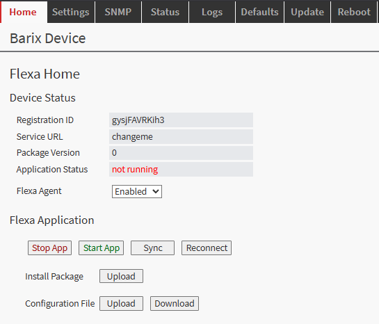
Navigate to the HOME tab in the main menu.
-
Locate the "Upload" button next to "Install Package" within the page –
⚠️ do not confuse it with the Upload button next to “Configuration File” -
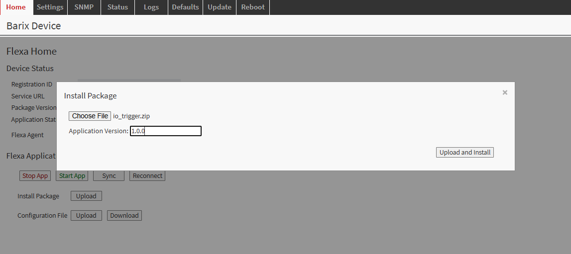
Click the file selection button and browse to io_trigger.zip downloaded from this page.
-
Choose and enter an appropriate version number for tracking purposes.
-
Click the UPLOAD button to begin the installation process.
Step 3: Device Reboot and Verification
After the upload completes, the Barionet device will automatically initiate a reboot sequence. The reboot process typically takes 30–40 seconds.
-
Wait for the device to complete its reboot cycle.
-
Reconnect to the web interface using the same IP address and credentials.
-
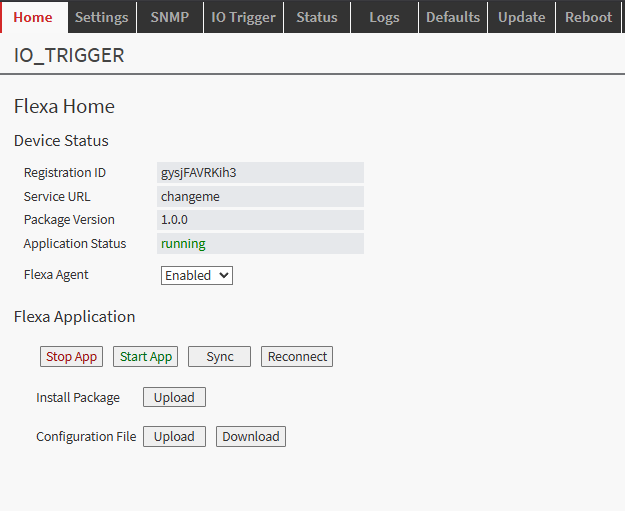
Navigate back to the HOME tab.
-
Verify that the IO Trigger application appears with a status of "running".
On the first run after installation, the application detects the number of connected UX8 extensions and automatically updates the configuration form to match the available hardware. The application will restart once automatically during this process. This is normal behaviour and only occurs on the first run or when the hardware configuration changes.
Configuration
After successfully installing the application, a new tab "IO Trigger" appears in the device web interface. All settings are configured from this tab.
The configuration form is organised into the following sections:
-
Input sections — one collapsible section per available digital input (4 built-in, plus 8 per detected UX8 - the web config form is automatically populated based on the number of UX8 connected)
-
Serial Port Settings — global baud rate and line format for the /dev/ttyS1 serial port
-
Logging — optional remote syslog configuration
NOTE: After making any changes, click “Save Changes” at the bottom of the form. The application restarts automatically and applies the new configuration.
Input Sections
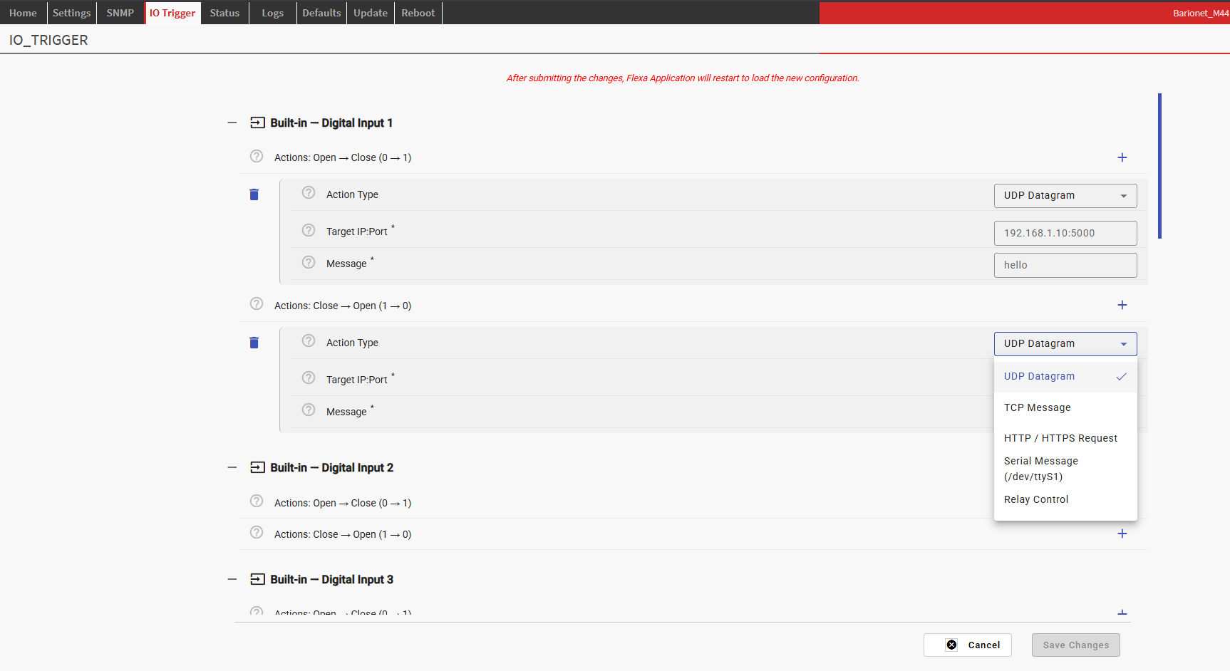
Each input section is collapsed by default. Expand the relevant input to configure it. Each input provides two independent action lists:
-
Actions: Open → Close (0→1) — fired when the input transitions from open (low) to closed (high)
-
Actions: Close → Open (1→0) — fired when the input transitions from closed (high) to open (low)
Up to 10 actions can be added to each list. Actions execute in order, sequentially.
Adding an Action
-
Expand the input section for the desired digital input.
-
Click the add button inside the relevant action list (0→1 or 1→0).
-
Select the Action Type from the dropdown.
-
Fill in the fields that appear for the selected action type.
-
Repeat to add additional actions (up to 10 per list).
-
Click Save Changes when done.
Action Types
UDP Datagram
Sends a UDP datagram to a target host when the input transitions.
|
Parameter |
Description |
Example |
|---|---|---|
|
Target IP:Port |
Destination address in IP:PORT format |
|
|
Message |
Payload string to send in the UDP datagram |
|
TCP Message
Opens a TCP connection to the target, sends a message, then closes the connection.
|
Parameter |
Description |
Example |
|---|---|---|
|
Target IP:Port |
TCP server address in IP:PORT format |
|
|
Message |
Text to send after connecting |
|
|
Connect Timeout (s) |
Maximum time to wait for connection |
|
HTTP / HTTPS Request
Sends an HTTP or HTTPS request to a target host. Supports all standard verbs and an optional request body.
|
Parameter |
Description |
Example |
|---|---|---|
|
Host:Port |
Target host with optional port. Prefix |
|
|
Path |
URL path for the request |
|
|
HTTP Verb |
Request method: GET, POST, PUT, PATCH, DELETE |
|
|
Body Format |
No Body, Plain Text, or JSON (sets Content-Type accordingly) |
|
|
Body |
Request body content (plain text string or JSON string) |
|
|
Verify SSL |
Enable to verify the server certificate. Disable for self-signed certificates. |
Unchecked |
|
Timeout (s) |
Maximum time to wait for a response |
|
NOTE: When using HTTPS with a self-signed certificate (e.g. on a local server or test machine), the Verify SSL Certificate checkbox must be unchecked. Leaving it checked with a self-signed cert will cause the request to fail with a connection error.
HTTP Body Format
|
Body Format |
Content-Type sent |
Use case |
|---|---|---|
|
No Body |
(none) |
GET, DELETE, or any verb that carries no payload |
|
Plain Text |
|
Simple string payloads |
|
JSON |
|
JSON API endpoints |
Serial Message
Writes a message to the serial port /dev/ttyS1. Serial port parameters (baud rate, parity, stop bits) are configured globally in the Serial Port Settings section.
|
Parameter |
Description |
Example |
|---|---|---|
|
Message |
Text to write to the serial port. Standard escape sequences ( |
|
|
Append CR+LF |
When checked, appends |
Unchecked |
Relay Control
Controls one or more relays on the Barionet or connected UX8 extensions.
|
Parameter |
Description |
Example |
|---|---|---|
|
Relays to Control |
Select one or more relays from the list. Built-in relays and UX8 relays are shown according to detected hardware. |
|
|
State |
Action to apply to the selected relay(s). See table below. |
|
|
Return After (s) |
Visible only when State = Timed. The relay returns to its previous state after this many seconds (1–3600). |
|
Relay State Options
|
State |
Behaviour |
|---|---|
|
ON |
Sets the relay to ON (energised), regardless of current state |
|
OFF |
Sets the relay to OFF (de-energised), regardless of current state |
|
Toggle |
Flips the relay to the opposite of its current state |
|
Timed |
Flips the relay to the opposite of its current state, then returns it to the original state after the configured number of seconds. Handled in a background thread — does not block other actions. |
Serial Port Settings
The serial port settings apply globally to all Serial Message actions. The port /dev/ttyS1 is opened once on first use and reused for all subsequent serial actions.
|
Parameter |
Options |
Default |
|---|---|---|
|
Baud Rate |
1200, 2400, 4800, 9600, 19200, 38400, 57600, 115200 |
|
|
Data Bits |
5, 6, 7, 8 |
|
|
Parity |
None, Even, Odd |
|
|
Stop Bits |
1, 2 |
|
Logging
The Logging section configures remote syslog for monitoring and debugging. This is particularly useful in production environments where direct console access is not available.
|
Parameter |
Description |
Default |
|---|---|---|
|
Enable Syslog |
Enables sending log messages to a remote syslog server |
Disabled |
|
Syslog Server |
IP address and port of the remote syslog server (IP:PORT format) |
|
Log messages are sent using facility LOCAL0. Typical log messages include input state changes, action execution results, and startup/shutdown events.
Startup Behaviour and UX8 Detection
The IO Trigger App uses a two-phase startup procedure to ensure the configuration form always matches the physical hardware.
Phase 1 — Hardware Detection
On every start, the application reads IO addresses 60007–60010 to detect how many UX8 extension modules are connected. It then compares this count against the value cached from the previous run.
If the count has changed (or on the very first run after installation):
-
The matching SDF file is selected — one of five pre-built configuration form definitions (
sdf_0ux8.jsonthroughsdf_4ux8.json) is copied toconfig/sdf.json -
The new count is cached to
config/ux8_count.txtfor comparison on the next start -
The application requests a restart via
barix-wdso the device web interface reloads the updated form
If the UX8 count is unchanged, Phase 1 completes instantly and the application proceeds directly to Phase 2 with no restart.
Phase 2 — Normal Operation
The application loads config.json, registers change notifications for all configured digital inputs, and enters the main loop. From this point it reacts to input transitions in real time, firing the configured actions in background threads so that multiple simultaneous events are handled independently.
NOTE: The automatic restart during Phase 1 only occurs when the hardware configuration changes. Under normal operation (no UX8 modules added or removed), the application starts directly into Phase 2 on every subsequent run, including after a configuration form save.
Technical Reference
Package Contents
|
File |
Description |
|---|---|
|
|
Application entry point. Contains startup logic, UX8 detection, and action executors. |
|
|
Flexa package descriptor. Defines the run command, tab name, and SDF pointer. |
|
|
Application name and version. |
|
|
Active configuration form definition (copied from the matching |
|
|
Form definition for base unit only (4 inputs). |
|
|
Form definition for base + 1 UX8 (12 inputs). |
|
|
Form definition for base + 2 UX8 (20 inputs). |
|
|
Form definition for base + 3 UX8 (28 inputs). |
|
|
Form definition for base + 4 UX8 (36 inputs). |
config.json Structure
The configuration is written automatically by Flexa when the user saves the IO Trigger form. The application reads it from config.json under the AppParam key. The structure follows the SDF section hierarchy:
{
  "AppParam": {
    "input_1": {
      "actions_0to1": [
        {
          "action_type": "http",
          "http_host": "https://192.168.1.10:8443",
          "http_path": "/api/trigger",
          "http_verb": "POST",
          "http_body_format": "json",
          "http_body": "{\"input\":1,\"state\":\"closed\"}",
          "http_verify_ssl": false,
          "http_timeout": 10
        }
      ],
      "actions_1to0": []
    },
    "serial": {
      "baud_rate": 9600,
      "data_bits": 8,
      "parity": "N",
      "stop_bits": 1
    },
    "logging": {
      "enable_syslog": true,
      "syslog_address": "192.168.1.50:514"
    }
  }
}
Action Execution Model
When a digital input changes state, the application fires its configured action list in a dedicated background thread. This means:
-
Multiple inputs can trigger simultaneously without blocking each other.
-
Actions within a single list execute sequentially, in the order they were configured.
-
A slow action (e.g. an HTTP request with a long timeout) does not delay actions on other inputs.
-
Timed relay return is handled in its own separate thread per relay, independent of the action thread.
Supported Python Packages
The application uses only pre-installed packages available on the Barionet M44 OS. No additional installation is required.
|
Package |
Version |
Used for |
|---|---|---|
|
|
2.23.0 |
HTTP and HTTPS actions |
|
|
3.4 |
Serial port actions |
|
|
built-in |
Digital input notifications and relay control |
Monitoring and Logging
Because SSH access to the Barionet M44 is not available in normal operation, all runtime diagnostics are delivered via the remote syslog facility. Enable syslog in the Logging section of the configuration form and point it to a machine running a syslog server.
Typical Log Messages
Startup
io_trigger: INFO UX8 extension #1 detected.
io_trigger: INFO UX8 units present: [1]
io_trigger: INFO SDF already matches 1 UX8 unit(s) — no restart needed.
io_trigger: INFO Phase 1 complete. Proceeding with 1 UX8 unit(s).
io_trigger: INFO Monitoring 12 inputs.
io_trigger: INFO Listening: Built-in DI-1  addr=201
io_trigger: INFO IO Trigger running. Waiting for input events ...
Input Events and Action Execution
io_trigger: INFO [Built-in DI-1] 0→1  (Open→Close) — firing 2 action(s)
io_trigger: DEBUG UDP → 192.168.1.10:5000  msg='DOOR_OPEN'
io_trigger: DEBUG HTTP POST https://192.168.1.5:8443/api/event → 200
io_trigger: INFO [UX8-1/DI-3] 1→0  (Close→Open) — firing 1 action(s)
io_trigger: DEBUG Relay addr=1 → TIMED 1 for 5s (will restore to 0)
io_trigger: DEBUG Relay addr=1 restored → 0 after 5s
Error Messages
io_trigger: ERROR HTTP action failed (POST https://192.168.1.5:8443/api/event): Connection refused
io_trigger: ERROR UDP action failed (192.168.1.10:5000): [Errno 111] Connection refused
io_trigger: ERROR Serial action: /dev/ttyS1 not available.
io_trigger: ERROR Relay action failed addr=1: [write error]
Common Issues
|
Symptom |
Likely Cause |
Resolution |
|---|---|---|
|
HTTP action fails with "Connection reset by peer" |
HTTPS URL sent to an HTTP port, or SSL verification enabled with a self-signed certificate |
Ensure the Host:Port includes the |
|
HTTP action fails with SSL certificate verification error |
Verify SSL is checked but the server presents a self-signed certificate |
Uncheck the Verify SSL Certificate option for that action. |
|
Actions do not fire after saving the config |
Normal — the app restarts on every config save |
Wait 5–10 seconds for the restart to complete. Check the HOME tab to confirm the app status is "running". |
|
Form shows only 4 inputs after connecting a UX8 |
UX8 was connected after the last app start |
The app detects UX8 only at startup. Stop and restart the app from the HOME tab to trigger re-detection. |
|
Serial messages not received |
Baud rate or format mismatch, or /dev/ttyS1 busy |
Verify the Serial Port Settings match the receiving device. Ensure no other app is using the serial port. |
|
Timed relay does not return |
App was stopped or restarted during the timed interval |
The timed return runs in memory. If the app restarts (e.g. after a config save) during the interval, the return will not complete. Design actions accordingly. |
Software Disclaimer
IMPORTANT:
This software application ("Software") is provided "AS IS" without warranty of any kind, express or implied, including but not limited to the warranties of merchantability, fitness for a particular purpose, and non-infringement. In no event shall the author, developer, or distributor be liable for any claim, damages, or other liability, whether in an action of contract, tort, or otherwise, arising from, out of, or in connection with the Software or the use or other dealings in the Software.
Use at Your Own Risk: The user assumes all responsibility and risk for the use of this Software. The author makes no representations or warranties regarding the accuracy, reliability, completeness, or timeliness of the Software or its suitability for any particular purpose.
No Support Obligation: The provision of this Software does not create any obligation to provide technical support, maintenance, updates, enhancements, or modifications. The Software is provided for educational and reference purposes only.
Third-Party Dependencies: This Software may utilize third-party libraries and components. The user is responsible for ensuring compliance with all applicable licences and terms of use for such dependencies.
Network and Security: The user is solely responsible for implementing appropriate security measures and network configurations. The author is not responsible for any security vulnerabilities, data breaches, or network disruptions that may result from the use of this Software.
Compliance: Users are responsible for ensuring that their use of this Software complies with all applicable laws, regulations, and organisational policies in their jurisdiction.
Limitation of Liability: Under no circumstances shall the total liability of the author exceed zero dollars ($0.00) for any damages arising out of or related to the use of this Software.
By using this Software, you acknowledge that you have read, understood, and agree to be bound by the terms of this disclaimer.