|
Version |
Changelog |
Date |
Download |
|---|---|---|---|
|
1.0.1 |
Initial Release |
Application Version: 1.0.1
Compatible Firmware: Flexa Firmware min. v2.3.2 (click to download)
Device Compatibility: Barionet M44, UX8 Extension
Overview
The TCP Command API provides a network interface for controlling and monitoring IO operations on the Barionet M44 device. This application is specifically designed to offer drop-in replacement compatibility for installations where legacy Barionet 50 or Barionet 100 devices are deployed, providing customers with a seamless upgrade path to the modern Barionet M44 hardware.
Key Features
-
Retro-compatible API: Uses the same IO Addressing scheme as legacy Barionet devices
-
Extended functionality: Leverages additional capabilities available on the Barionet M44
-
TCP-based communication: Simple, reliable protocol for real-time control from a connected peer. One TCP connection at a time is supported.
-
Flexible notifications: Real-time state change for built-in IOs and subscription-based notifications
-
Security features: IP filtering and password authentication of individual messages
-
UX8 extension support: Automatic detection and configuration of UX8 expansion modules
-
Broadcast support: Network-wide device discovery capabilities
Compatible Hardware
Primary Platform: The application is designed for Barionet M44 devices running the Flexa Firmware v2.3.2
Extension Support: When (2x) UX8 extension modules are connected via USB, the system gains an additional 16 digital inputs and 16 relays, bringing the total capacity to 20 inputs and 20 relays per device.
IMPORTANT NOTICE
This implementation supports up to 4 UX8 extension modules, with corresponding addresses reserved in the IO addressing table. However, at the time of this documentation, only configurations with up to 2 UX8 extensions have been fully tested and validated. While the system is designed to handle 4 extensions, configurations using 3 or 4 UX8 modules have not yet undergone comprehensive testing.
Application API
Communication Protocol
The API uses TCP protocol for all communications. Commands are sent as text strings and responses are returned in a structured format.
Default Port: 12302 (configurable)
Maximum Message Size: 256 bytes
Character Encoding: UTF-8
Command Terminators
The following terminators are accepted for incoming commands:
-
\r(carriage return) -
\n(line feed) -
\00(null terminator) -
Any combination of the above
All responses are terminated with carriage return \r (0x0d).
Command Format
Commands must be sent in lowercase. Invalid case will return cmderr\r or command failed\r
Supported Commands
1. version
Returns device and firmware information.
Request: version
Response: version,Product_Name Image_Name Firmware_Version\r
Example Response: version,Barionet_M44 core-image-barix-flexa 2.3.2\r
Error Response: command failed\r (if system information cannot be retrieved)
2. c=65535
Returns the DHCP hostname configuration. This command supports broadcast responses for device discovery.
by default the dhcp hostname is empty causing the command to fail. Configure the DHCP Hostname in the “SETTINGS” tab of the device under the “Network” settings.
Request: c=65535
Response: <BARIONET><NAME>hostname</NAME></BARIONET>\r
Example Response: <BARIONET><NAME>BarionetM44</NAME></BARIONET>\r
No Hostname Configured: <BARIONET><NAME>DHCP HOSTNAME NOT CONFIGURED</NAME></BARIONET>\r (if not configured)
Error Response: command failed\r
Note: This command must be typed exactly as shown (case-sensitive).
3. getio,address
Reads the current value of an IO address.
Request: getio,A where A is the address number
Response: state,A,V\r where V is the current value
Example Request: getio,201
Example Response: state,201,1\r
Error Response: cmderr\r (if address is invalid or not readable)
Validation:
-
Address must be a valid, readable IO address
-
See Appendix for valid address ranges
4. setio,address,value
Writes a value to an IO address.
Request: setio,A,V where A is the address and V is the value to be written
Response: state,A,V\r confirming the written value
Example Request: setio,1,1
Example Response: state,1,1\r
Error Response: cmderr\r (if address is not writable or value is invalid)
Special Functions for 1-bit addresses (relays, outputs, virtual IOs):
-
Toggle Function (value = 999):
-
Toggles the current state (0→1 or 1→0)
-
Example:
setio,1,999toggles relay 1
-
-
Timed Function (value = 2-998 or 1000-9999):
-
Sets output to 1 and automatically resets to 0 after value/10 seconds
-
Example:
setio,2,100enables relay 2 for 10 seconds -
Example:
setio,3,3000enables relay 3 for 300 seconds -
Multiple timers can run simultaneously
-
New timer overwrites existing timer for same address
-
Manual
setio,A,0cancels active timer
-
Validation:
-
Address must be writable
-
Value must be within valid range for address bit size:
-
1-bit: 0-1 (plus special values 2-998, 999, 1000-9999)
-
4-bit: 0-15
-
16-bit: 0-65535
-
32-bit: 0-4294967295
-
5. iolist
Returns a summary of system IO configuration.
Request: iolist
Response: io,AI,DI,AO,DO,0,R,T\r
Where:
-
AI = Number of analog inputs
-
DI = Number of digital inputs
-
AO = Number of analog outputs
-
DO = Number of digital outputs
-
0 = Reserved (always 0) - N° of IR interfaces on legacy devices
-
R = Number of relays
-
T = Number of temperature sensors detected
Example Response for BM44 with no UX8 connected and 5 temp sensors: io,4,4,0,0,0,4,5\r
Error Response: cmderr\r
Command Concatenation
Multiple commands can be sent in a single message using & as separator.
Format: command1&command2&command3
Response: response1&response2&response3\r
Example:
-
Request:
setio,1,1&getio,201&version -
Response:
state,1,1&state,201,0&version,Barionet_M44 core-image-barix-flexa 2.3.1\r
Password Authentication
When a password is configured, all commands must be prefixed with the authentication string.
Format: a=PASSWORD&command
Example: a=secret123&getio,1
Error Response: operation not allowed\r (if password is incorrect or missing)
Note: For concatenated commands, the password is only required once at the beginning:
-
a=PASSWORD&command1&command2&command3
For clear reasons a password cannot contain the “&” character.
TCP Subscription & Notification Service
The TCP Command API provides a push-based notification system that automatically sends IO state change messages to the connected TCP peer without the peer needing to poll individual addresses. This eliminates continuous polling and makes the integration reactive and efficient.
Notifications are delivered as statechange,A,V\r messages, where A is the IO address and V is the new value. They are sent asynchronously, at any time, over the same TCP connection used for commands.
Note: Notification messages are one-way. The peer does not acknowledge them and must not send a response.
Configuration Parameters
The notification behaviour is controlled by two parameters, both located in the web configuration interface:
TCP_initial_state_subscriptions
Controls whether an initial IO state dump is sent when a TCP peer connects, and whether the built-in local IO addresses are permanently monitored for state changes during the session.
Only BM44 built-in addresses are monitored. UX8 extension addresses are excluded from the monitoring.
Accepted values:
-
"None"— No initial dump is sent. No automatic subscriptions are created at connect time. -
"LocalIO"— On connect, an immediate state dump of the 8 built-in local IO addresses is sent (relays 1–4 and digital inputs 201–204). These addresses are then monitored for the entire session duration.
TCP_add_IO_state_subscriptions
Controls whether getio and setio commands dynamically subscribe their target address for future state change notifications. The subscription remains active for the duration of the current TCP session and is cleared when the peer disconnects.
Accepted values:
-
"None"— Commands do not create any subscriptions. No dynamic notifications are generated. -
"With getio/setio"— Every time agetioorsetiocommand is sent for an eligible address, that address is subscribed. Future external state changes on that address will generate astatechangenotification for the remainder of the session.
Behaviour Matrix
|
TCP_initial_state_subscriptions |
TCP_add_IO_state_subscriptions |
Behaviour |
|---|---|---|
|
|
|
No state change messages are sent at any time. |
|
|
|
Initial IO dump is sent on connect. State change messages are sent for built-in relays (1–4) and digital inputs (201–204) whenever their state changes externally. |
|
|
|
Initial IO dump is sent on connect. State change messages are sent for all LocalIO addresses plus any additional address explicitly queried or written via |
|
|
|
No initial dump. State change messages are sent only for addresses that have been explicitly addressed by a |
Initial IO State Dump (LocalIO mode)
When TCP_initial_state_subscriptions is set to "LocalIO", the application immediately sends the current state of the 8 built-in local addresses as soon as the TCP connection is established, before any command is processed.
Addresses included in the initial dump:
-
1, 2, 3, 4— Built-in relay outputs -
201, 202, 203, 204— Built-in digital inputs
Format of the initial dump:
statechange,1,0\r
statechange,2,0\r
statechange,3,1\r
statechange,4,0\r
statechange,201,0\r
statechange,202,1\r
statechange,203,0\r
statechange,204,0\r
Note: The dump reflects the actual current state of each address at the moment of connection. Values shown above are examples only.
Runtime State Change Notifications
Digital Inputs
Digital input addresses (201–204) generate a statechange notification every time their physical state changes, regardless of what caused the change. These are always externally driven (by field wiring), so every transition is always reported.
// Digital input 1 closes (circuit closed):
statechange,201,1\r

// Digital input 1 opens (circuit open):
statechange,201,0\r
Relay Outputs
Relay addresses (1–4, and 11–42 when UX8 extensions are present) generate statechange notifications only when their state is changed by an external source — for example, via the command line, another API, or another application interacting with the Barionet.
Important: When a relay is controlled by a setio command sent through this TCP API, the statechange notification is suppressed. The peer already knows the new state from the state,A,V\r response returned by setio. Sending an additional statechange would be redundant and could confuse the application.
// Peer sends:   setio,1,1
// App responds: state,1,1\r       ← confirmed immediately
// NO statechange is generated for this event.

// Later, relay 1 is toggled externally (e.g. via CLI):
// App sends:    statechange,1,0\r  ← pushed automatically
Virtual IO and Other 1-bit Addresses
All other eligible 1-bit writable addresses (virtual IOs, RS232 RTS, USB control, and UX8 digital inputs when acting as virtual IOs) follow the same suppression rule as relays: state changes triggered by a setio command are suppressed; changes from any other source generate a statechange notification.
Dynamic Subscriptions (With getio/setio mode)
When TCP_add_IO_state_subscriptions is set to "With getio/setio", each getio or setio command acts as an implicit subscription request for its target address. After a command is processed, any future external state change on that address will automatically generate a statechange notification for the remainder of the session.
Subscribing via getio
// Peer sends:
getio,201

// App responds immediately:
state,201,0\r

// Address 201 is now subscribed. Later, when input 1 closes:
statechange,201,1\r    ← pushed automatically
Subscribing via setio
// Peer sends:
setio,1,1

// App responds immediately:
state,1,1\r

// Address 1 is now subscribed. Later, if relay 1 is toggled externally:
statechange,1,0\r    ← pushed automatically

// Note: the setio command itself does NOT generate a statechange.
Subscription Scope and Lifetime
-
Per-address: each address is subscribed individually when first addressed by
getioorsetio. -
Session-scoped: subscriptions are active only for the duration of the current TCP connection. When the peer disconnects, all dynamic subscriptions are cleared.
-
De-duplicated: sending multiple
getioorsetiocommands for the same address does not create duplicate subscriptions. -
No cross-session persistence: a reconnecting peer must re-issue its
getio/setiocommands to re-establish subscriptions.
Eligible Addresses for Notifications
Not all IO addresses are eligible for state change notifications. The following table lists all eligible address ranges and their notification behaviour.
|
Address Range |
IO Type |
Notification Behaviour |
|---|---|---|
|
|
Built-in relays |
Notified on external state change. |
|
|
Built-in digital inputs |
Notified on every state change (inputs are always externally driven). |
|
|
UX8 relays (if UX8 detected) |
Notified on external state change. |
|
|
Virtual IO (if no UX8) |
Notified on external state change. |
|
|
UX8 digital inputs (if UX8) |
Notified on every state change. |
|
|
Virtual IO (if no UX8) |
Notified on external state change. |
|
|
Virtual IO / other 1-bit writable |
Eligible for subscription via |
Note: Multi-bit addresses (16-bit, 32-bit, 4-bit) are not eligible for
statechangenotifications regardless of configuration.
Interaction with the Timed setio Function
The setio command supports a timed function: when the value argument is in the range 2–998 or 1000–9999, the application writes 1 to the address immediately and automatically writes 0 after value / 10 seconds.
From a notification perspective, the peer receives only the immediate state,A,1\r response and a statechange notification when the timer expires and the address toggles.
// Peer sends:   setio,2,100   (write 1, reset after 10 seconds)
// App responds: state,2,1\r   ← immediate response
//
// After 10 seconds the app internally resets relay 2 to 0 and sends
// statechange,2,0
Combined Configuration Example
The following walkthrough shows the full message flow for a typical session with both settings active:
"TCP_initial_state_subscriptions": "LocalIO"
"TCP_add_IO_state_subscriptions": "With getio/setio"
── TCP peer connects ──────────────────────────────────────────────────

// App sends initial dump immediately:
statechange,1,0\r
statechange,2,0\r
statechange,3,0\r
statechange,4,0\r
statechange,201,0\r
statechange,202,0\r
statechange,203,0\r
statechange,204,0\r

── Peer issues commands ───────────────────────────────────────────────

Peer:  getio,219          // subscribe virtual IO 219
App:   state,219,0\r

Peer:  setio,1,1          // write relay 1 — subscribe address 1
App:   state,1,1\r        // no statechange (setio suppressed)

── External events ────────────────────────────────────────────────────

// Digital input 1 closes (external):
App:   statechange,201,1\r

// Relay 1 toggled externally (e.g. via CLI):
App:   statechange,1,0\r

// Virtual IO 219 written externally:
App:   statechange,219,1\r

// Relay 2 changes externally (not yet subscribed — no notification)

── Peer disconnects ───────────────────────────────────────────────────
// All dynamic subscriptions cleared. Reconnection starts fresh.
Quick Reference
Notification message format:
statechange,<ADDRESS>,<VALUE>\r
Key rules:
-
setiowrites are suppressed — nostatechangeis sent for TCP-API-triggered writes. -
The initial dump is sent only when
"LocalIO"is configured. -
Dynamic subscriptions require
"With getio/setio"to be configured. -
Subscriptions are cleared on disconnect and must be re-established on reconnect.
-
Multi-bit addresses (16-bit, 32-bit, 4-bit) are never notifiable.
-
Timed
setioauto-resets do not generatestatechangenotifications.
Tip: For full real-time monitoring with minimal setup, use
"TCP_initial_state_subscriptions": "LocalIO"together with"TCP_add_IO_state_subscriptions": "With getio/setio". This gives you an immediate state snapshot on connect plus automatic subscriptions for every address your application interacts with.
Installation Process
Installing the application requires uploading the package zipped file directly to your Barionet device through its web interface. This process is straightforward but requires careful attention to ensure proper installation.
NOTE: If your Barionet M44 is already running an application you must RESET TO DEFAULTS before proceeding and installing a new one.
Step 1: Access the Device Web Interface
-
Open your web browser and navigate to your Barionet device's IP address
-
Enter your administrator username and password when prompted
-
Wait for the main interface to load completely before proceeding
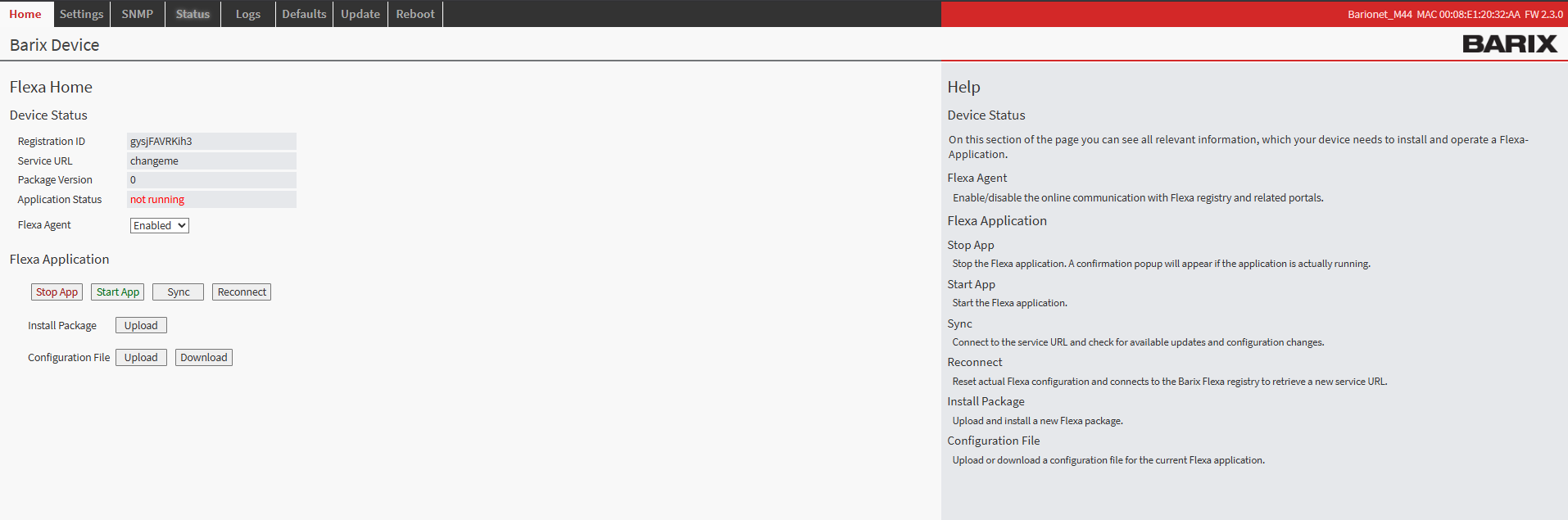
Barionet M44 User Interface
Step 2: Upload the Application Package
-
Navigate to the HOME tab in the main menu
-
Locate the "Upload" button next to “Install Package” within the page
-
Click the file selection button and browse to the “package.zip” which was downloaded from this page
-
Choose an appropriate version number for tracking purposes (this can be any number you prefer for identification)
-
Click the UPLOAD button to begin the installation process
Step 3: Device Reboot and Verification
After the upload completes, your Barionet device will automatically initiate a reboot sequence. This reboot is necessary to properly integrate the new application into the system. The reboot process typically takes 30..40s
-
Wait for the device to complete its reboot cycle
-
Reconnect to the web interface using the same IP address and credentials
-
Navigate back to the HOME tab
-
Verify that the IO Tunnel application appears with a status of "running"
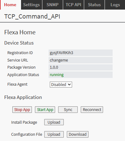
Configuration Overview
Once successfully installed, the configuration interface becomes available through the TCP API tab in your device's web interface. This dedicated configuration page provides access to all settings necessary to establish communication between the device and the server.
The configuration system is designed to be intuitive, each setting includes helpful descriptions and validation to prevent configuration errors that could disrupt communication.
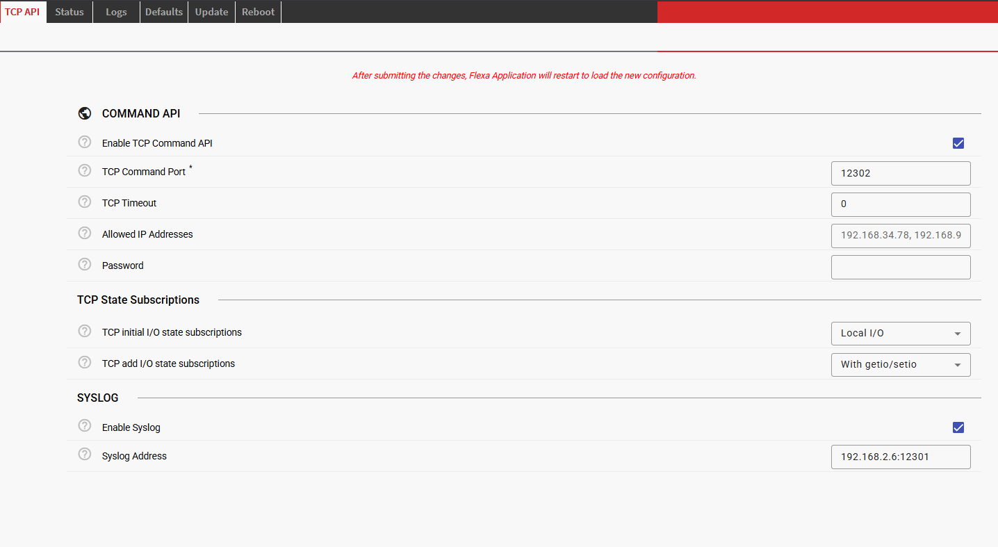
|
Parameter |
Default |
Description |
|---|---|---|
|
|
Enabled |
Enable/disable the TCP API server |
|
|
12302 |
TCP port for receiving commands |
|
|
"" |
Comma-separated list of allowed IP addresses to connect with the TCP server |
|
|
"" |
Authentication password (empty = disabled) |
|
|
Local I/O |
Enable/Disable notification service for built-in I/Os and provides a dump upon TCP connection establishment |
|
|
None |
Enable/Disable the dynamic subscription service for notifications with getio/setio commands |
|
|
Disabled |
Enable syslog logging |
|
|
"" |
Syslog server (format: "IP:PORT") |
Security Features
Allowed IP Addresses (IP Filtering)
Restrict access to the TCP API to specific IP addresses by configuring Allowed IP Addresses.
Format: Comma-separated IP addresses
Example: "192.168.1.100, 192.168.1.101, 10.0.0.50"
Default: Empty string (all IPs allowed)
When an IP is blocked:
-
No response is sent to the client
-
Attempt is logged (if syslog is enabled)
Password Protection
Enable password authentication by setting the Password parameter.
Configuration: "password": "your_secret_password"
Usage: Prefix all commands with a=password&
Example: a=mysecret&getio,1
Syslog Integration
Enable remote logging by configuring Syslog parameters in the web configuration.
Logged Events:
-
Server startup/shutdown
-
All incoming TCP messages
-
Command processing results
-
Authentication failures
-
Blocked IP attempts
-
IO state changes (if notifications enabled)
-
Timer events
-
Errors and warnings
Syslog Facility: LOCAL0
Appendix: IO Address Reference
Full description of Barionet M44 IO Addresses that can be controlled by the TCP API application:
Built-in IO
|
Address Range |
Type |
R/W |
Description |
|---|---|---|---|
|
1-4 |
1-bit |
R/W |
Built-in relays 1-4 |
|
9 |
1-bit |
R/W |
RS232 RTS output |
|
10 |
1-bit |
R/W |
Virtual IO |
|
201-204 |
1-bit |
R |
Digital inputs 1-4 |
|
209 |
1-bit |
R |
RS232 CTS input |
|
301-304 |
1-bit |
R/W |
Input pullups 1-4 |
|
401-404 |
32-bit |
R/W |
Input counters 1-4 |
|
501-504 |
16-bit |
R |
Analog inputs 1-4
|
UX8 Extension IO
IMPORTANT NOTICE
This implementation supports up to 4 UX8 extension modules, with corresponding addresses reserved in the IO addressing table. However, at the time of this documentation, only configurations with up to 2 UX8 extensions have been fully tested and validated. While the system is designed to handle 4 extensions, configurations using 3 or 4 UX8 modules have not yet undergone comprehensive testing.
|
Address Range |
Type |
R/W |
Description |
|---|---|---|---|
|
11-18 |
1-bit |
R/W |
UX8 #1 relays (virtual IO if not detected) |
|
19-26 |
1-bit |
R/W |
UX8 #2 relays (virtual IO if not detected) |
|
27-34 |
1-bit |
R/W |
UX8 #3 relays (virtual IO if not detected) |
|
35-42 |
1-bit |
R/W |
UX8 #4 relays (virtual IO if not detected) |
|
211-218 |
1-bit |
R |
UX8 #1 digital inputs (virtual IO if not detected) |
|
219-226 |
1-bit |
R |
UX8 #2 digital inputs (virtual IO if not detected) |
|
227-234 |
1-bit |
R |
UX8 #3 digital inputs (virtual IO if not detected) |
|
235-242 |
1-bit |
R |
UX8 #4 digital inputs (virtual IO if not detected) |
|
411-418 |
32-bit |
R/W |
UX8 #1 input counters |
|
419-426 |
32-bit |
R/W |
UX8 #2 input counters |
|
427-434 |
32-bit |
R/W |
UX8 #3 input counters |
|
435-442 |
32-bit |
R/W |
UX8 #4 input counters |
|
511-518 |
16-bit |
R |
UX8 #1 Analog inputs (virtual registers if not detected).
|
|
519-526 |
16-bit |
R |
UX8 #2 Analog inputs (virtual registers if not detected).
|
|
527-524 |
16-bit |
R |
UX8 #3 Analog inputs (virtual registers if not detected).
|
|
535-542 |
16-bit |
R |
UX8 #4 Analog inputs (virtual registers if not detected).
|
|
1212..1219 |
1-bit |
R/W |
UX8#1 Analog Input Enable (write “1” to enable) |
|
1220-1227 |
1-bit |
R/W |
UX8#2 Analog Input Enable (write “1” to enable) |
|
1228-1235 |
1-bit |
R/W |
UX8#3 Analog Input Enable (write “1” to enable) |
|
1235-1243 |
1-bit |
R/W |
UX8#4 Analog Input Enable (write “1” to enable) |
|
60007-60010 |
1-bit |
R |
UX8 detection (1=connected) |
Virtual IO
|
Address Range |
Type |
R/W |
Description |
|---|---|---|---|
|
43-100 |
1-bit |
R/W |
Virtual IO bits |
|
109-200 |
1-bit |
R/W |
Virtual IO bits |
|
210 |
1-bit |
R/W |
Virtual IO bit |
|
243-300 |
1-bit |
R/W |
Virtual IO bits |
|
309-400 |
1-bit |
R/W |
Virtual IO bits |
|
409-410 |
32-bit |
R/W |
Virtual registers |
|
443-500 |
32-bit |
R/W |
Virtual registers |
|
509-510 |
16-bit |
R/W |
Virtual registers |
|
543-600 |
16-bit |
R/W |
Virtual registers |
|
751-1200 |
16-bit |
R/W |
Virtual registers |
System Information
|
Address Range |
Type |
R/W |
Description |
|---|---|---|---|
|
651-700 |
32-bit |
R |
Temperature Sensor Addresses (1-wire) - lower 32bits (signed integer is returned. Must be converted in HEX to get the “lower portion” of the sensor serial number) |
|
701-750 |
32-bit |
R |
Temperature Sensor Addresses (1-wire) - higher 32bits (signed integer is returned. Must be converted in HEX to get the “higher portion” of the sensor serial number) |
|
1201 |
16-bit |
R |
Device supply current (mA) |
|
1202 |
16-bit |
R |
Device supply voltage (mV) |
|
1203 |
16-bit |
R |
CPU temperature (mC) |
|
1204 |
32-bit |
R |
System uptime (seconds) |
|
1205 |
16-bit |
R |
Hardware type ID |
|
1206 |
16-bit |
R |
Firmware version |
|
1207 |
1-bit |
R/W |
USB enable/disable |
|
60001 |
16-bit |
R |
Serial port count |
|
60002 |
16-bit |
R |
Relay count (including UX8 Extensions if detected) |
|
60003 |
16-bit |
R |
Digital output count (including UX8 Extensions if detected) |
|
60004 |
16-bit |
R |
Digital input count (including UX8 Extensions if detected) |
|
60005 |
16-bit |
R |
Analog output count (including UX8 Extensions if detected) |
|
60006 |
16-bit |
R |
Analog input count (including UX8 Extensions if detected) |
Software Disclaimer
IMPORTANT:
This software application ("Software") is provided "AS IS" without warranty of any kind, express or implied, including but not limited to the warranties of merchantability, fitness for a particular purpose, and non-infringement. In no event shall the author, developer, or distributor be liable for any claim, damages, or other liability, whether in an action of contract, tort, or otherwise, arising from, out of, or in connection with the Software or the use or other dealings in the Software.
Use at Your Own Risk: The user assumes all responsibility and risk for the use of this Software. The author makes no representations or warranties regarding the accuracy, reliability, completeness, or timeliness of the Software or its suitability for any particular purpose.
No Support Obligation: The provision of this Software does not create any obligation to provide technical support, maintenance, updates, enhancements, or modifications. The Software is provided for educational and reference purposes only.
Third-Party Dependencies: This Software may utilize third-party libraries and components. The user is responsible for ensuring compliance with all applicable licenses and terms of use for such dependencies.
Network and Security: The user is solely responsible for implementing appropriate security measures and network configurations. The author is not responsible for any security vulnerabilities, data breaches, or network disruptions that may result from the use of this Software.
Compliance: Users are responsible for ensuring that their use of this Software complies with all applicable laws, regulations, and organizational policies in their jurisdiction.
Limitation of Liability: Under no circumstances shall the total liability of the author exceed zero dollars ($0.00) for any damages arising out of or related to the use of this Software.
By using this Software, you acknowledge that you have read, understood, and agree to be bound by the terms of this disclaimer.