
MQTT Client for Barionet Flexa
|
Version |
Changelog |
Date |
Download |
|---|---|---|---|
|
1.0.0 |
Initial Release |
||
|
2.0.0 |
|
|
Application Version: 2.0.0
Compatible Firmware: Flexa Firmware min. v2.3.4 (click to download)
Device Compatibility: Barionet M44, UX8 Extension
Overview
The MQTT Client App turns the Barionet into an MQTT-controlled I/O gateway. Every
input, output, relay, counter, analog channel, temperature sensor and system
register of the device is exposed through a simple, addressable MQTT topic scheme
for reading and writing, with automatic state-change publishing for
digital inputs and relays.
Key Features
-
Relay Control: MQTT-based control of up to 20 relays
-
Digital Input Monitoring: Real-time monitoring of up to 20 digital inputs
-
Hardware Auto-Detection: Automatic detection of built-in IOs and UX8 IO extensions
-
High Availability: Automatic MQTT re-connection with exponential backoff
-
Production Logging: Remote syslog integration with structured logging
-
Health Monitoring: Built-in health checks and system monitoring
-
Graceful Shutdown: Proper cleanup and status reporting
Supported Hardware
-
Barionet Base Unit: Relays/Inputs 1-4 (always available)
-
1x UX8 Extension: Relays/Inputs 5-12 (auto-detected)
-
2x UX8 Extensions: Relays/Inputs 13-20 (auto-detected)
Compatible Hardware
Primary Platform: The MQTT Application is designed for Barionet M44 devices running the Flexa Firmware v2.3.3
Extension Support: Up to (2x) UX8 extension module can be connected via USB, the system gains an additional 16 digital inputs and 16 relays, bringing the total capacity to 20 inputs and 20 relays per set.
Installation Process
Installing the MQTT Application requires uploading a package file directly to your Barionet device through its web interface. This process is straightforward but requires careful attention to ensure proper installation.
NOTE: If your Barionet M44 is already running an application you must RESET TO DEFAULTS before proceeding and installing a new one.
Step 1: Access the Device Web Interface
-
Open your web browser and navigate to your Barionet device's IP address
-
Enter your administrator username and password when prompted
-
Wait for the main interface to load completely before proceeding
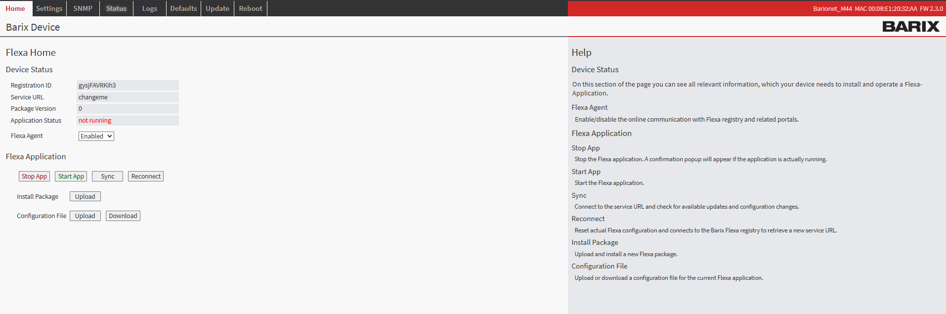
Barionet M44 User Interface
Step 2: Upload the Application Package
-
Navigate to the HOME tab in the main menu
-
Locate the "Upload" button next to “Install Package” within the page
-
Click the file selection button and browse to the “package.zip” which was downloaded from this page
-
Choose an appropriate version number for tracking purposes (this can be any number you prefer for identification)
-
Click the UPLOAD button to begin the installation process
Step 3: Device Reboot and Verification
After the upload completes, your Barionet device will automatically initiate a reboot sequence. This reboot is necessary to properly integrate the new application into the system. The reboot process typically takes 30..40s
-
Wait for the device to complete its reboot cycle
-
Reconnect to the web interface using the same IP address and credentials
-
Navigate back to the HOME tab
-
Verify that the MQTT Application appears with a status of "running"
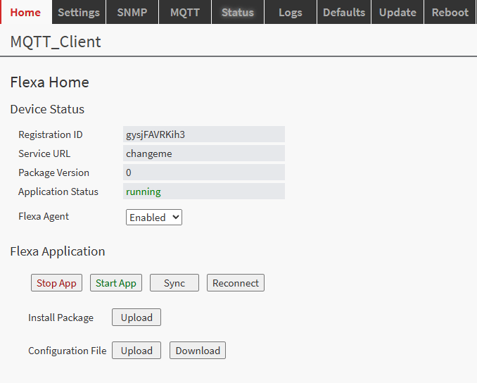
Configuration
After successfully installing the application on your Barionet you will notice a new tab “MQTT” where the application can be configured.
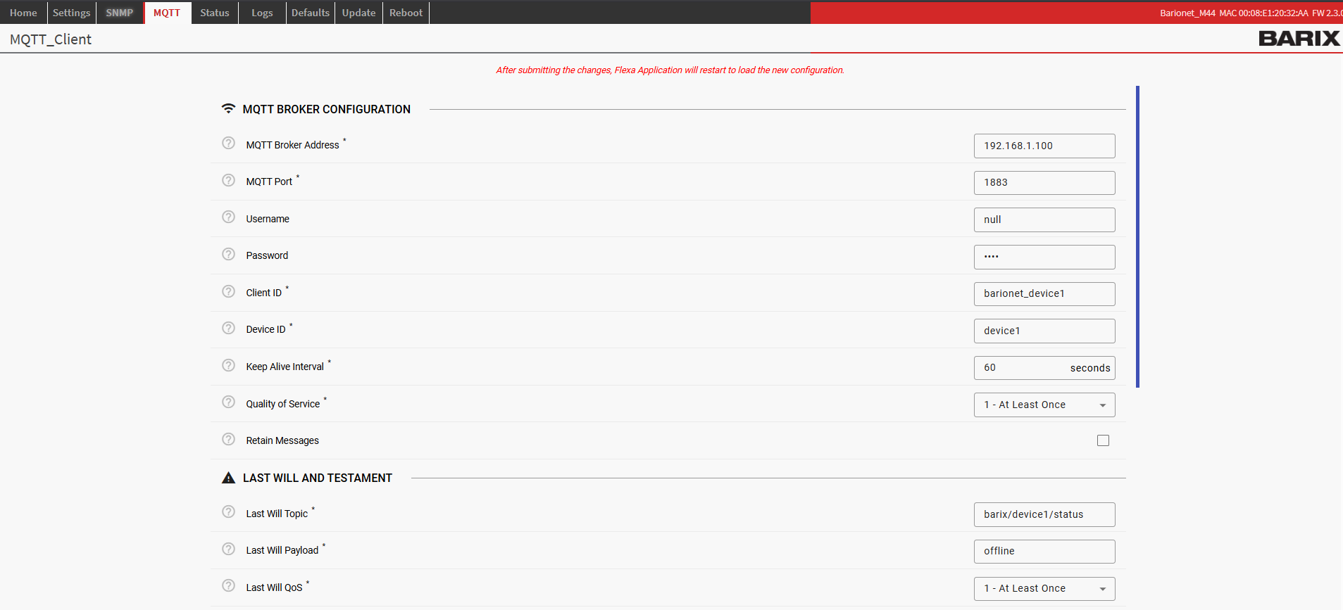
The configuration is distributed across the following sections:
MQTT Configuration Parameters
Required Parameters
|
Parameter |
Description |
Example |
|---|---|---|
|
|
MQTT broker IP address or hostname |
|
|
|
MQTT broker port number |
|
|
|
Unique MQTT client identifier |
|
|
|
Device ID used in MQTT topics |
|
Optional Parameters
|
Parameter |
Default |
Range |
Description |
|---|---|---|---|
|
|
|
|
MQTT authentication username (use |
|
|
|
|
MQTT authentication password (use |
|
|
|
10-3600 |
MQTT connection keepalive interval (seconds) |
|
|
|
0, 1, 2 |
Quality of Service level for MQTT messages |
|
|
|
|
Default retain flag for published messages |
Last Will and Testament Parameters
|
Parameter |
Default |
Description |
|---|---|---|
|
|
|
Topic for Last Will message |
|
|
|
Payload for Last Will message |
|
|
|
QoS level for Last Will message |
|
|
|
Retain flag for Last Will message |
Hardware Configuration Parameters
|
Key |
Default |
Notes |
|---|---|---|
|
|
|
Seconds between input/relay polls (0.01–10) |
|
|
|
Digital-input debounce time in seconds; |
|
|
|
Publish current input/relay states on every (re)connect |
Logging Configuration Parameters
|
Parameter |
Default |
Options |
Description |
|---|---|---|---|
|
|
|
DEBUG, INFO, WARNING, ERROR, CRITICAL |
Application log level |
|
|
|
|
Enable/disable remote syslog logging |
|
|
|
|
Remote syslog server IP address (i.e. “192.168.75.43”) |
|
|
|
1-65535 |
Remote syslog server port |
Application Configuration Parameters
|
Key |
Default |
Notes |
|---|---|---|
|
|
|
Seconds between initial connection attempts |
|
|
|
Initial-connection attempts before giving up |
|
|
|
If the I/O engine makes no progress for this long, the app exits so the supervisor restarts it |
|
|
|
Max outbound messages buffered when the broker is slow/unreachable |
|
|
|
Max unacknowledged QoS>0 messages in flight |
|
|
|
Reserved (not used in this version) |
MQTT Topics
Topic structure
All topics are built from the configurable Device ID (mqtt_device_id, default device1) and an IO address (see Section 5):
|
Topic |
Direction |
Purpose |
|---|---|---|
|
|
App → Broker |
Connection status: |
|
|
Client → App |
Write a value to an address |
|
|
Client → App |
Request the current value of an address |
|
|
App → Broker |
Reply to a read request |
|
|
App → Broker |
State change of a monitored input/relay, and confirmation of every successful write |
The QoS and retain flag used by the app when it publishes response, state and
the online status are taken from mqtt_qos and mqtt_retain. The online
status is always published retained so newly connected clients immediately
learn the device state.
Wildcard subscriptions
barix/device1/#              # everything from the device
barix/device1/state/+        # all input/relay/output state changes
barix/device1/response/+     # all read replies
barix/device1/status         # online / offline
Reading values
Publish an (empty) message to read/{address}. The app replies on
response/{address} with the current value as a decimal integer.
# Read relay 1
mosquitto_pub -h BROKER -t barix/device1/read/1 -m ""
# -> barix/device1/response/1   0

# Read digital input 1 (address 201)
mosquitto_pub -h BROKER -t barix/device1/read/201 -m ""
# -> barix/device1/response/201 0

# Read supply voltage (mV), address 1202
mosquitto_pub -h BROKER -t barix/device1/read/1202 -m ""
# -> barix/device1/response/1202 12833
Any readable address can be read on demand, including analog inputs, counters,
temperatures and system/hardware-info registers.
Writing values
Publish the integer value as the payload to write/{address}. On success the
app applies the value and publishes a confirmation on state/{address}.
# Turn relay 1 ON
mosquitto_pub -h BROKER -t barix/device1/write/1 -m "1"
# -> barix/device1/state/1 1

# Turn relay 1 OFF
mosquitto_pub -h BROKER -t barix/device1/write/1 -m "0"
# -> barix/device1/state/1 0

# Write a 16-bit virtual register (address 509)
mosquitto_pub -h BROKER -t barix/device1/write/509 -m "12345"
# -> barix/device1/state/509 12345
Note: payloads are integers only. Words such as
ON/OFFare not
accepted; use1/0.
Special functions for 1-bit outputs
For 1-bit outputs — relays, the RS232 RTS output, digital outputs and 1-bit
virtual I/Os — the written value has special meanings:
|
Value written |
Action |
|---|---|
|
|
Set output OFF |
|
|
Set output ON |
|
|
Toggle the current state (0↔1) |
|
|
Timed: switch ON now, automatically OFF after value ÷ 10 seconds |
|
|
Timed: switch ON now, automatically OFF after value ÷ 10 seconds |
Examples:
# Toggle relay 1
mosquitto_pub -h BROKER -t barix/device1/write/1 -m "999"

# Relay 2 ON for 10 seconds (100 / 10 = 10 s)
mosquitto_pub -h BROKER -t barix/device1/write/2 -m "100"

# Virtual IO 58 ON for 300 seconds (3000 / 10 = 300 s)
mosquitto_pub -h BROKER -t barix/device1/write/58 -m "3000"
Timer behaviour
-
Timers on different addresses run independently and simultaneously; each
resets when its own time expires. -
Sending a new timer to an address that already has a running timer
replaces the previous one. -
Sending a manual
0/1/999to an address with a running timer
cancels the timer and applies the manual command immediately. -
On a graceful shutdown, any output still running a timer is switched OFF.
-
On an unexpected shutdown/restart, running timers are lost.
State-change publishing
The app continuously monitors digital inputs and relays. When one of them
changes state, the new value is published on state/{address}:
barix/device1/state/201 1      # digital input 1 closed
barix/device1/state/201 0      # digital input 1 open
barix/device1/state/1   1      # relay 1 switched on
-
Digital inputs are debounced (
input_debounce_interval, default 50 ms): a
new input level must remain stable for the debounce time before it is
published, so mechanical switch-contact bounce does not flood the broker. -
Initial state on connect is configurable (
publish_initial_state, default
off):-
off — only subsequent changes are published; use a
readto obtain a
current value at any time. -
on — the current value of every monitored digital input and relay is
published onstate/{address}on each (re)connection to the broker, so
subscribers immediately learn the full device state.
-
-
Counters, analog inputs, temperatures and system registers are not
auto-published; read them on demand viaread/{address}.
IO Address Map
Values are decimal. "R" = readable, "W" = writable. Addresses marked "(UX8)" are
only available when the corresponding UX8 extension is detected at startup
(addresses 60007–60010). When the extension is absent, reads and writes to those
addresses are rejected as not available.
|
Address(es) |
Function |
Bits |
Access |
|---|---|---|---|
|
1–8 |
Relays 1–8 |
1 |
R/W |
|
9 |
RS232 RTS output |
1 |
R/W |
|
10 |
Virtual I/O |
1 |
R/W |
|
11–42 |
UX8 relays (#1: 11–18, #2: 19–26, #3: 27–34, #4: 35–42) |
1 |
R/W (UX8) |
|
43–100, 109–200, 243–300, 309–400 |
Virtual I/O bits |
1 |
R/W |
|
101–108 |
Digital outputs 1–8 (reserved on M44) |
1 |
R/W |
|
201–208 |
Digital inputs 1–8 |
1 |
R |
|
209 |
RS232 CTS input |
1 |
R |
|
210 |
Virtual I/O |
1 |
R/W |
|
211–242 |
UX8 digital inputs |
1 |
R (UX8) |
|
301–304 |
Pull-up control for digital inputs 1–4 |
1 |
R/W |
|
401–408 |
Digital input counters 1–8 |
32 |
R/W |
|
409–410, 443–500 |
Virtual registers |
32 |
R/W |
|
411–442 |
UX8 digital input counters |
32 |
R/W (UX8) |
|
501–508 |
Analog inputs 1–8 (mV) |
16 |
R |
|
509–510, 543–600, 751–1200 |
Virtual registers |
16 |
R/W |
|
511–542 |
UX8 analog inputs (mV) |
16 |
R (UX8) |
|
601–650 |
Temperature sensors (m°C) |
16 |
R |
|
651–700 / 701–750 |
Temp sensor address (lower / higher) |
32 |
R |
|
1201 |
Device supply current (mA) |
16 |
R |
|
1202 |
Device supply voltage (mV) |
16 |
R |
|
1203 |
Device CPU temperature (m°C) |
16 |
R |
|
1204 |
Device uptime (seconds) |
32 |
R |
|
1205 |
Hardware Type ID |
16 |
R |
|
1206 |
Firmware version |
16 |
R |
|
1207 |
USB control |
1 |
R/W |
|
1208–1211 |
LED control |
4 |
R/W |
|
1212–1244 |
UX8 input pull-up controls |
1 |
R/W (UX8) |
|
60001 |
Number of serial ports |
16 |
R |
|
60002 |
Number of relays |
16 |
R |
|
60003 |
Number of digital outputs |
16 |
R |
|
60004 |
Number of digital inputs |
16 |
R |
|
60005 |
Number of analog outputs |
16 |
R |
|
60006 |
Number of analog inputs |
16 |
R |
|
60007–60010 |
UX8 #1–#4 detected (0/1) |
1 |
R |
Write validation
A write is rejected (logged as a warning, no action taken) when:
-
the address does not exist;
-
the address is read-only (e.g. a digital input, analog input, temperature);
-
the address requires a UX8 extension that is not connected;
-
the value is out of range for the address bit-size (for a 1-bit output any
value other than0,1,999, or the timed ranges2–998/1000–9999).
Hardware Support
Hardware Detection
The application automatically detects available hardware on startup by checking for the existence of connected UX8 devices.
Hardware Configurations
Base Barionet Unit
-
Relays: 1-4
-
Inputs: 1-4
-
Status: Always available
Base + 1x UX8 Extension
-
Relays: 1-12
-
Inputs: 1-12
-
Status: Auto-detected based on highest available I/O number
Base + 2x UX8 Extensions
-
Relays: 1-20
-
Inputs: 1-20
-
Status: Auto-detected based on highest available I/O number
Hardware Status Logging
The application logs hardware detection results:
INFO - Hardware detection complete: 12 relays, 12 inputs, 1 UX8 extensions
I/O Numbering
Hardware I/O is numbered sequentially:
-
Base Unit: 1, 2, 3, 4
-
First UX8: 5, 6, 7, 8, 9, 10, 11, 12
-
Second UX8: 13, 14, 15, 16, 17, 18, 19, 20
Monitoring and Logging
Log Levels
The application supports five log levels (configured via logging_level):
|
Level |
Description |
Use Case |
|---|---|---|
|
|
Detailed diagnostic information |
Development and troubleshooting |
|
|
General information messages |
Normal operation monitoring |
|
|
Warning messages for potential issues |
Production monitoring |
|
|
Error messages for failed operations |
Production alerts |
|
|
Critical errors causing application failure |
Emergency alerts |
Log Destinations
Syslog Logging
-
When: Always enabled (unless
logging_syslog_enabled: false) -
Format:
hostname barionet[PID]: LEVEL - message -
Facility: LOCAL0 (hardcoded)
-
Use: Production logging and monitoring
Log Message Types
Startup/Shutdown Messages
INFO - Loading configuration from config.json
INFO - Starting hardware detection...
INFO - Hardware detection complete: 8 relays, 8 inputs, 1 UX8 extensions
INFO - Starting Barionet MQTT application...
INFO - MQTT connected successfully
INFO - Barionet MQTT application started successfully
Hardware Operation Messages
INFO - Relay 3 set to ON
INFO - Input 7 state changed to 1
WARNING - Failed to read initial state for input 12: Permission denied
MQTT Communication Messages
INFO - MQTT connection attempt 1/10
INFO - Subscribed to barix/device1/relay/1/set
DEBUG - Received MQTT message: barix/device1/relay/3/set = ON
DEBUG - Published to barix/device1/relay/3/status: ON
Error Messages
ERROR - Failed to connect to MQTT broker: [Errno 111] Connection refused
WARNING - MQTT connection lost, attempting to reconnect...
ERROR - Failed to set relay 5 to True: [Errno 2] No such file or directory
Health Check Messages
INFO - Health check: 8 relays, 8 inputs, MQTT connected: True
Software Disclaimer
IMPORTANT:
This software application ("Software") is provided "AS IS" without warranty of any kind, express or implied, including but not limited to the warranties of merchantability, fitness for a particular purpose, and non-infringement. In no event shall the author, developer, or distributor be liable for any claim, damages, or other liability, whether in an action of contract, tort, or otherwise, arising from, out of, or in connection with the Software or the use or other dealings in the Software.
Use at Your Own Risk: The user assumes all responsibility and risk for the use of this Software. The author makes no representations or warranties regarding the accuracy, reliability, completeness, or timeliness of the Software or its suitability for any particular purpose.
No Support Obligation: The provision of this Software does not create any obligation to provide technical support, maintenance, updates, enhancements, or modifications. The Software is provided for educational and reference purposes only.
Third-Party Dependencies: This Software may utilize third-party libraries and components. The user is responsible for ensuring compliance with all applicable licenses and terms of use for such dependencies.
Network and Security: The user is solely responsible for implementing appropriate security measures and network configurations. The author is not responsible for any security vulnerabilities, data breaches, or network disruptions that may result from the use of this Software.
Compliance: Users are responsible for ensuring that their use of this Software complies with all applicable laws, regulations, and organizational policies in their jurisdiction.
Limitation of Liability: Under no circumstances shall the total liability of the author exceed zero dollars ($0.00) for any damages arising out of or related to the use of this Software.
By using this Software, you acknowledge that you have read, understood, and agree to be bound by the terms of this disclaimer.