
|
Version |
Changelog |
Date |
Download |
|---|---|---|---|
|
1.0.0 |
Initial Release |
|
|
|
1.0.1 |
Fixed: memory leak in background IO poll process |
|
Application Version: 1.0.0
Compatible Firmware: Flexa Firmware min. v2.3.4 (click to download)
Device Compatibility: Barionet M44, UX8 Extension
IMPORTANT NOTICE
This implementation supports up to 4 UX8 extension modules, with corresponding addresses reserved in the IO addressing table. However, at the time of this documentation, only configurations with up to 1 UX8 extension have been fully tested and validated. While the system is designed to handle 4 extensions, configurations using 2 or more UX8 modules have not yet undergone comprehensive testing.
Overview
A reference Flexa App that turns a Barix Barionet M44 into a Modbus TCP server
(slave). A PLC, SCADA system or HMI acting as Modbus master can read every input the
Barionet has and drive its relays, subject to a write policy the operator configures in
the device web UI.
How it fits together
   PLC / SCADA  ──Modbus TCP──▶  MODBUS_IO_SERVER  ──D-Bus──▶  io-mapping  ──▶  hardware
    (master)          :502          (this app)                  (firmware)      relays, DIs,
                                                                                analogs, 1-Wire
The M44 firmware has no Modbus service of its own — io-mapping is the abstraction
layer that gives every physical and virtual I/O a numeric address. This app maps those
addresses onto the four Modbus register spaces and serves them over TCP.
Two implementation choices are worth knowing before you fork this app:
-
Reads are cached, writes are not. One
iomapping.read_value()costs ~3.6 ms on an
M44; a batchedread_values()costs ~0.7 ms per address. A master polling 40 registers
every 100 ms cannot afford a D-Bus round trip per register, so a background thread
refreshes an I/O cache and Modbus reads are answered from it. The Poll interval
setting is therefore the worst-case age of any value. Writes go straight to
io-mappingand then update the cache, so a read-back immediately after a write
returns the new value. -
The write policy lives in the datastore.
PolicySlaveContext.validate()is the
only pymodbus hook that sees both the target address and the function code, so it can
allow a read and reject a write on the same address. Denied writes get exception code
0x02 (ILLEGAL DATA ADDRESS).
Register map
Addressing is zero-based (zero_mode=True). Tools that use the classic 1-based
0xxxx/1xxxx/3xxxx/4xxxx notation show coil 0 as 00001, discrete input 0 as 10001,
input register 0 as 30001 and holding register 0 as 40001.
Addresses not listed are intentional gaps and answer with ILLEGAL DATA ADDRESS —
that is correct Modbus behaviour, not a fault.
Coils — FC01 read, FC05/FC15 write (bits, read/write)
|
Coil |
IO address |
Group |
Description |
|---|---|---|---|
|
0–3 |
1–4 |
relay |
Relays 1–4 (onboard) |
|
4–11 |
11–18 |
relay |
UX8 #1 relays 1–8 |
|
12–19 |
19–26 |
relay |
UX8 #2 relays 1–8 |
|
20–27 |
27–34 |
relay |
UX8 #3 relays 1–8 |
|
28–35 |
35–42 |
relay |
UX8 #4 relays 1–8 |
|
40–43 |
301–304 |
pullup |
Digital input pull-ups 1–4 |
|
50–79 |
43–72 |
virtual |
Virtual bits 1–30 (scratch, no hardware effect) |
|
90 |
1207 |
system |
USB ports enable |
Discrete inputs — FC02 (bits, read-only)
|
Discrete input |
IO address |
Description |
|---|---|---|
|
0–3 |
201–204 |
Digital inputs 1–4 |
|
4–11 |
211–218 |
UX8 #1 digital inputs 1–8 |
|
12–19 |
219–226 |
UX8 #2 digital inputs 1–8 |
|
20–27 |
227–234 |
UX8 #3 digital inputs 1–8 |
|
28–35 |
235–242 |
UX8 #4 digital inputs 1–8 |
|
40 |
209 |
RS-232 CTS input |
|
50–53 |
60007–60010 |
UX8 module #1–#4 detected |
Input registers — FC04 (16 bit, read-only)
|
Input register |
IO address |
Description |
|---|---|---|
|
0–3 |
501–504 |
Analog inputs 1–4, mV |
|
4–11 |
511–518 |
UX8 #1 analog inputs 1–8, mV |
|
12–19 |
519–526 |
UX8 #2 analog inputs 1–8, mV |
|
20–27 |
527–534 |
UX8 #3 analog inputs 1–8, mV |
|
28–35 |
535–542 |
UX8 #4 analog inputs 1–8, mV |
|
40–89 |
601–650 |
Temperature sensors 1–50, m°C (divide by 1000) |
|
100–107 |
401–404 |
Digital input counters 1–4, 32 bit, high word first |
|
200 |
1201 |
Supply current, mA |
|
201 |
1202 |
Supply voltage, mV |
|
202 |
1203 |
CPU temperature, m°C |
|
203–204 |
1204 |
Device uptime, seconds, 32 bit, high word first |
|
205 |
1205 |
Hardware type (82 = Barionet M44) |
|
206 |
1206 |
Firmware version (0x0234 = v2.3.4) |
|
207 |
60002 |
Relay count including UX8 |
|
208 |
60004 |
Digital input count including UX8 |
|
209 |
60006 |
Analog input count including UX8 |
|
210 |
app |
Seconds since the last Modbus request |
|
211 |
app |
Watchdog state: 0 = armed/idle, 1 = tripped |
|
212 |
app |
Currently connected Modbus masters |
Holding registers — FC03 read, FC06/FC16 write (16 bit, read/write)
|
Holding register |
IO address |
Group |
Description |
|---|---|---|---|
|
10–39 |
543–572 |
virtual |
Virtual 16-bit registers 1–30 |
Value conventions
-
Values wider than 16 bits (counters, uptime) occupy two registers, high word first.
-
Anything that does not fit 16 bits — including negative temperatures in m°C — is
carried as 16-bit two's complement. -
Registers for hardware that is absent (an unfitted UX8, an uninstalled temperature
sensor) stay readable and return 0.
Installation Process
Installing the application requires uploading the package zipped file directly to your Barionet device through its web interface. This process is straightforward but requires careful attention to ensure proper installation.
NOTE: If your Barionet M44 is already running an application you must RESET TO DEFAULTS before proceeding and installing a new one.
Step 1: Access the Device Web Interface
-
Open your web browser and navigate to your Barionet device's IP address
-
Enter your administrator username and password when prompted
-
Wait for the main interface to load completely before proceeding
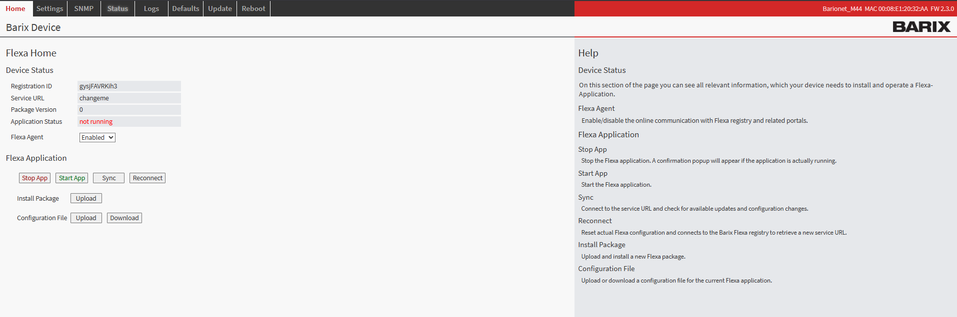
Barionet M44 User Interface
Step 2: Upload the Application Package
-
Navigate to the HOME tab in the main menu
-
Locate the "Upload" button next to “Install Package” within the page
-
Click the file selection button and browse to the “<package>.zip” which was downloaded from this page
-
Choose an appropriate version number for tracking purposes (this can be any number you prefer for identification)
-
Click the UPLOAD button to begin the installation process
Step 3: Device Reboot and Verification
After the upload completes, your Barionet device will automatically initiate a reboot sequence. This reboot is necessary to properly integrate the new application into the system. The reboot process typically takes 30..40s
-
Wait for the device to complete its reboot cycle
-
Reconnect to the web interface using the same IP address and credentials
-
Navigate back to the HOME tab
-
Verify that the application status appears with a status of "running"
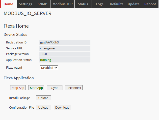
Configuration Overview
Once successfully installed, the configuration interface becomes available through the Application tab in your device's web interface. This dedicated configuration page provides access to all settings necessary to establish communication between the device and the server.
The configuration system is designed to be intuitive, each setting includes helpful descriptions and validation to prevent configuration errors that could disrupt communication.
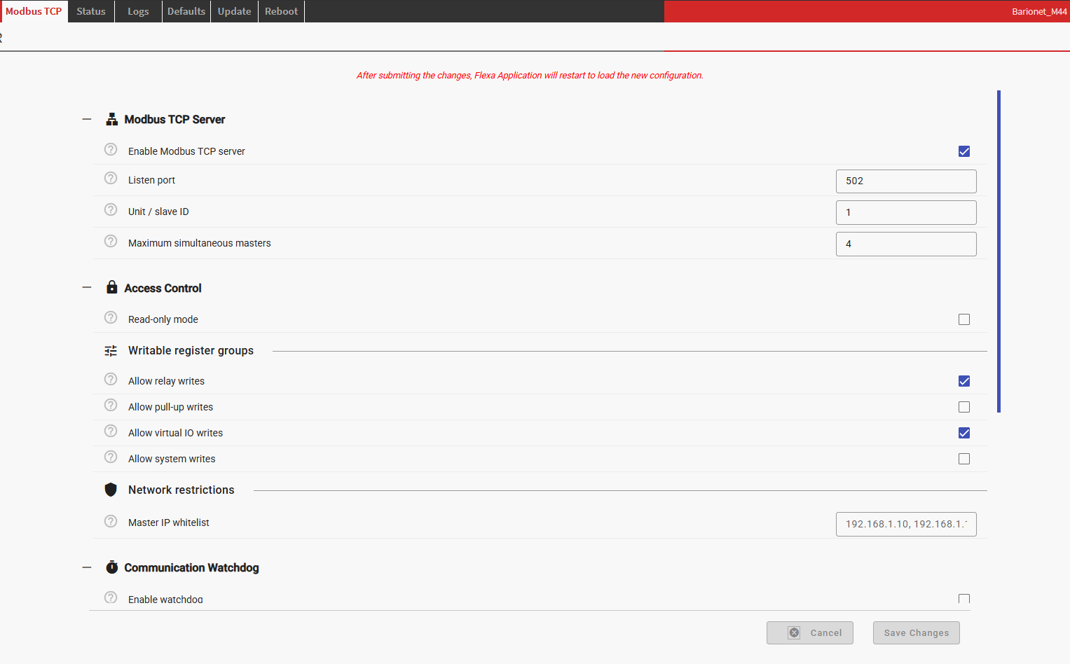
Configuration (web UI → Modbus TCP tab)
|
Section |
Setting |
Default |
Notes |
|---|---|---|---|
|
Modbus TCP Server |
Enable |
on |
Turns the slave off without uninstalling |
|
|
Listen port |
502 |
|
|
|
Unit / slave ID |
1 |
Requests for other unit IDs get no reply |
|
|
Max simultaneous masters |
4 |
Excess connections are closed; 0 = unlimited |
|
Access Control |
Read-only mode |
off |
Master switch — rejects every write function |
|
|
Allow relay writes |
on |
Coils 0–35 |
|
|
Allow pull-up writes |
off |
Coils 40–43 |
|
|
Allow virtual IO writes |
on |
Coils 50–79, holding 10–39 |
|
|
Allow system writes |
off |
Coil 90, holding 0–3 |
|
|
Master IP whitelist |
(empty) |
Comma-separated; empty = any master |
|
Communication Watchdog |
Enable |
off |
|
|
|
Communication timeout |
30 s |
Modbus silence before the safe state is applied |
|
|
Startup grace period |
60 s |
Watchdog stays inactive for this long after start |
|
|
Safe state action |
Open all relays |
Open all / close all / fixed pattern / report only |
|
|
Relay 1–4 safe pattern |
|
Only for the pattern action |
|
|
Include UX8 relays |
off |
Only for open-all / close-all |
|
IO Polling |
Poll interval |
250 ms |
Worst-case age of a value read over Modbus |
|
|
Temperature sensors installed |
4 |
Only this many 1-Wire sensors are polled |
|
|
Poll UX8 extension IO |
Auto |
Auto = only modules detected at startup |
|
Logging |
Log level |
INFO |
|
|
|
Enable Syslog / Syslog Server |
off |
The only debugging channel on a sealed device |
Submitting the form writes config.json and restarts the app — it always starts from
a clean state and never relies on anything held in memory beforehand.
Modbus TCP Server
Enable Modbus TCP server — server.enable, boolean, default on
Turns the Modbus slave on or off without uninstalling the package. When off, the app
starts, logs server disabled in configuration -- idling and then sits idle rather than
exiting — a Flexa app that exits is restarted by the platform watchdog, which would loop
forever. Nothing binds the port and the IO poller does not run, so the app costs
essentially nothing while disabled. Use this to take the device off a live Modbus network
without losing your configuration.
Listen port — server.listen_port, 1–65535, default 502
The TCP port the server binds to, on all interfaces. 502 is the registered Modbus port
and what masters assume by default. Change it only if something else on the device already
holds 502, or if you deliberately want the service on a non-standard port. Ports below
1024 need root, which Flexa apps have. If the bind fails the app logs
cannot bind 0.0.0.0:<port> and stops — check the log if the service seems absent.
Unit / slave ID — server.unit_id, 1–247, default 1
The Modbus unit identifier this device answers to. Requests carrying any other unit ID get
no reply at all rather than an exception, which is the friendlier behaviour when
several devices share a gateway or a serial bridge downstream. If your master reports
timeouts on every register, a unit ID mismatch is the first thing to check — the symptom
is silence, not an error code.
Maximum simultaneous masters — server.max_connections, 0–32, default 4
How many Modbus TCP connections may be open at once. A connection beyond the limit is
accepted by the TCP stack and then closed immediately, which the client sees as
"connection reset by peer". Set 0 for no limit. The limit protects the device from a
master that reconnects without closing its old sockets — a common failure mode that
otherwise accumulates connections until memory runs out. Input register 212 reports how
many masters are currently connected, so you can see how close you are to the limit.
Access Control
This section is the "control decisions" surface: it decides what a Modbus master is
allowed to change. Denied writes are answered with exception code 0x02 (ILLEGAL DATA
ADDRESS) and logged at WARNING level with the function code and address, so a rejected
write is visible in the log rather than failing silently. Reads are never restricted —
an address that is blocked for writing stays fully readable.
Read-only mode — access.read_only, boolean, default off
Master switch. When on, every write function (FC05, FC06, FC15, FC16) is rejected
regardless of the four group switches below, and the startup log records
access policy: read-only (all writes rejected). This is the setting to use when the
Barionet is purely a data source for a SCADA system and must never be actuated from the
network — commissioning a new master, for instance, without any risk of it driving your
plant.
Allow relay writes — access.allow_relay_writes, boolean, default on
Governs coils 0–35: the four onboard relays and all UX8 extension relays. This is the one
group that is on by default, because driving relays is the usual reason to install this
app. Turning it off leaves the relay states readable while making them untouchable from
the network.
Allow pull-up writes — access.allow_pullup_writes, boolean, default off
Governs coils 40–43, the pull-up resistors on digital inputs 1–4. Off by default because
changing a pull-up alters how its input reads — a master that writes these can silently
change the meaning of your input data, which is rarely what you want at runtime. Enable it
only if you genuinely need to reconfigure input biasing remotely.
Allow virtual IO writes — access.allow_virtual_writes, boolean, default on
Governs coils 50–79 and holding registers 10–39: scratch bits and registers with no
hardware effect whatsoever. They are useful as a handshake area between the master and
anything else running on the device — mode flags, setpoints, a heartbeat the master writes
and another app reads. Safe to leave on, since nothing physical can move as a result.
Allow system writes — access.allow_system_writes, boolean, default off
Governs coil 90 (USB ports enable) and holding registers 0–3 (user LED colour and
brightness). Off by default because these change device-level behaviour rather than
process IO. The LEDs are genuinely useful as a remote status indicator — driving LED
colour from a PLC to show plant state is a neat trick — but enable this deliberately.
Master IP whitelist — access.ip_whitelist, string, default empty
Comma-separated list of IP addresses permitted to connect, e.g.
192.168.1.10, 192.168.1.11. Leave empty to accept any master. A connection from an
address not on the list is closed immediately on connect and logged as
connection from <ip> rejected: not in the IP whitelist; the client sees a connection
reset. This is a coarse filter, not authentication — Modbus TCP has no authentication at
all, and an address can be spoofed — but it stops accidental cross-connection on a shared
plant network, which is the realistic risk. Exact addresses only; ranges and CIDR are not
supported.
Communication Watchdog
The only place the app makes a decision on its own. Everything in this section is hidden
in the UI until Enable watchdog is ticked.
Enable watchdog — watchdog.enable, boolean, default off
When on, a background thread checks once per second how long it has been since the last
Modbus request of any kind — read or write, from any master. If that exceeds the timeout,
the app drives the relays to the configured safe state, logs at ERROR level, and sets
input register 211 to 1.
The behaviour is deliberately one-shot: the safe state is applied once, and the app
does not repeat it or restore the previous relay states when the master returns. The
master owns the relays again the moment it is back. Input register 211 returns to 0 within
a second of traffic resuming, and the log records watchdog re-armed.
Communication timeout — watchdog.timeout_s, 1–3600 s, default 30
Seconds of Modbus silence before the safe state is applied. Set it to several times your
master's normal poll period — a watchdog that trips on ordinary jitter is worse than none.
If the master polls every second, 10–30 s is sensible; if it polls once a minute, this
must be well above 60.
Startup grace period — watchdog.startup_grace_s, 0–3600 s, default 60
Seconds after app start during which the watchdog stays inactive. This exists because the
app comes up before the master reconnects — after a device reboot, or after any config
save. Without a grace period every restart would trip the watchdog and drive your relays.
Make it comfortably longer than the worst-case time for your master to notice the device
and reconnect.
Safe state action — watchdog.action, default Open all relays
What to do when the watchdog trips:
-
Open all relays (
all_off) — de-energise everything. The right default for most
plant: loss of control means stop. -
Close all relays (
all_on) — energise everything. For fail-closed designs, e.g. a
valve that must be driven shut on loss of comms. -
Apply a fixed pattern to relays 1–4 (
pattern) — a per-relay safe state, for when
some outputs should drop and others should hold or engage. -
Do nothing (report only) (
none) — no relays are touched; the trip is still logged
and still visible in input register 211. Useful for observing how often comms actually
drop before committing to an action that moves hardware.
Relay 1–4 safe pattern — watchdog.relay_pattern, default 0,0,0,0
Visible only when the action is "pattern". Four comma-separated values, 0 = open,
1 = closed, applied to onboard relays 1–4 in order. UX8 relays are not covered by the
pattern action — use open-all or close-all if you need them included.
Include UX8 extension relays — watchdog.include_ux8, boolean, default off
Visible only for the open-all and close-all actions. Extends the safe state to the
relays of every UX8 module detected at startup, in addition to the four onboard relays.
Off by default so that adding an extension never silently widens the blast radius of a
watchdog trip.
IO Polling
These settings trade freshness against device load. Modbus reads are answered from a
cache that a background thread refreshes; nothing here affects writes, which always go
straight to the hardware.
Poll interval — polling.poll_interval_ms, 20–10000 ms, default 250
How often the cache is refreshed, and therefore the worst-case age of any value a
master reads. Reading one IO address costs roughly 0.7 ms in a batch, so a full sweep of
the default map takes on the order of 100 ms. If you set an interval shorter than one
sweep, the poller simply runs continuously — it never overlaps sweeps or queues up — and
logs a DEBUG line noting the overrun. Lower it for fast digital inputs; raise it to 1000 ms
or more if you are only trending slow analog values and want the CPU back.
Temperature sensors installed — polling.temp_sensor_count, 0–50, default 4
How many 1-Wire sensors to poll, mapped onto input registers 40 upward. The map always
exposes all 50 slots; this only controls how many are actually read from the hardware.
Unpolled slots stay readable and return 0. Since each sensor adds to every sweep, setting
this to the number you actually have — or 0 if none — is the cheapest way to shorten the
poll cycle.
Poll UX8 extension IO — polling.poll_ux8, default Auto
-
Auto — poll only the UX8 modules detected at startup. Right for almost everyone.
-
Always poll all four modules — poll all 96 UX8 addresses whether or not the modules
are present. Absent modules read 0. Only useful if detection is unreliable on your unit. -
Never poll UX8 IO — skip UX8 entirely and shorten the sweep, even if modules are
fitted. Their registers then read 0.
Detection happens at startup only, so restart the app (or save the config form) after
adding or removing an extension module.
Logging
There is no SSH on a sealed production device, so syslog is the only way to see what the
app is doing in the field.
Log level — logging.log_level, default INFO
-
Error — failures only: bind failures, io-mapping read/write errors, watchdog trips.
-
Warning — adds denied writes and rejected connections. A good production setting if
INFO is too chatty: you still see every security-relevant event. -
Info — adds startup detail (detected hardware, the full register map, the active
access policy) and every master connect/disconnect. The default, and what you want when
commissioning. -
Debug — adds poll-overrun notices. pymodbus's own logging is deliberately capped at
WARNING regardless of this setting, because it logs every frame and would flood a
syslog server.
Enable Syslog — logging.enable_syslog, boolean, default off
Sends log output to a remote syslog server, facility LOCAL0, in addition to stdout
(which Flexa captures). If the handler cannot be created — bad address, DNS failure — the
app logs the problem locally and carries on rather than refusing to start.
Syslog Server — logging.syslog_address, string, default empty
The server as IP:port, e.g. 192.168.1.10:514. The port may be omitted, in which case
514 is used. Ignored unless Enable Syslog is ticked.
Watchdog semantics
If no Modbus request of any kind arrives for Communication timeout seconds, the app
drives the relays to the configured safe state, logs at ERROR level, and sets input
register 211 to 1. It is one-shot: it does not repeat, and it does not restore the
previous relay states when the master returns — the master owns them again as soon as it
is back. Input register 211 returns to 0 within a second of traffic resuming.
The startup grace period exists because the app comes up before the master reconnects;
without it, every restart would trip the watchdog.
Quick check with pymodbus
Run the below code snippet on a machine where pymodbus is available:
#!/usr/bin/env python3
"""Test / diagnostic client for MODBUS_IO_SERVER on a Barionet M44.

Works with both pymodbus API generations:
  * <= 3.7  -> read_coils(addr, count, slave=1)
  * >= 3.8  -> read_coils(addr, count=count, device_id=1)

Usage: python test_modbus.py [host] [port] [unit_id] [relay_hold_seconds]

Sections:
  1. Snapshot     -- reads every mapped block once.
  2. Input test   -- interactive: asks you to close a contact and prints what
                     comes back over Modbus, sample by sample.
  3. Relay test   -- energises relays 1-4 for the hold period, then releases.
                     Asks for confirmation first.

WARNING: the relay test physically actuates relays 1-4.
"""

import inspect
import sys
import time

import pymodbus
from pymodbus.client import ModbusTcpClient

HOST = sys.argv[1] if len(sys.argv) > 1 else "192.168.2.20"
PORT = int(sys.argv[2]) if len(sys.argv) > 2 else 502
UNIT = int(sys.argv[3]) if len(sys.argv) > 3 else 1
HOLD_S = int(sys.argv[4]) if len(sys.argv) > 4 else 5

# pymodbus renamed the unit-id keyword from "slave" to "device_id" in 3.8,
# and made "count" keyword-only at the same time.
_params = inspect.signature(ModbusTcpClient.read_coils).parameters
UNIT_KW = "device_id" if "device_id" in _params else "slave"
UNIT_ARG = {UNIT_KW: UNIT}

INTERACTIVE = sys.stdin is not None and sys.stdin.isatty()


def read(fn, address, count):
    return fn(address, count=count, **UNIT_ARG)


def show(tag, response, attr, count=None):
    if response.isError():
        print("%-16s ERROR: %s" % (tag, response))
        return None
    values = getattr(response, attr)
    # Modbus packs bit responses into whole bytes, so asking for 4 coils returns
    # 8 bits -- the last 4 are protocol padding. Trim them off.
    if count is not None:
        values = values[:count]
    print("%-16s %s" % (tag, values))
    return values


def ask(prompt):
    """Wait for Enter. Returns False if the user asked to skip."""
    try:
        answer = input(prompt + " [Enter = go, s = skip] ").strip().lower()
    except (EOFError, KeyboardInterrupt):
        print()
        return False
    return answer != "s"


# ==========================================================================
# 1. SNAPSHOT
# ==========================================================================
def snapshot(client):
    print("--- snapshot ---")
    show("relays 1-4:", read(client.read_coils, 0, 4), "bits", 4)
    show("digital in 1-4:", read(client.read_discrete_inputs, 0, 4), "bits", 4)
    show("pull-ups 1-4:", read(client.read_coils, 40, 4), "bits", 4)
    show("analog mV:", read(client.read_input_registers, 0, 4), "registers")

    system = show("supply/CPU:", read(client.read_input_registers, 200, 3), "registers")
    if system:
        print("%-16s %d mA, %.2f V, CPU %.1f C"
              % ("decoded:", system[0], system[1] / 1000.0, system[2] / 1000.0))

    app = show("app regs:", read(client.read_input_registers, 210, 3), "registers")
    if app:
        print("%-16s idle %d s, watchdog %s, %d master(s) connected"
              % ("decoded:", app[0], "TRIPPED" if app[1] else "ok", app[2]))


# ==========================================================================
# 2. DIGITAL INPUT TEST
# ==========================================================================
#
# Prints the raw Modbus payload as well as the decoded value, because the two
# answer different questions: the raw byte proves what actually came back on
# the wire, the decoded value proves how this script interpreted it.


def read_inputs(client):
    """Return (bits[0:8], raw_byte, counters[0:4]) or None on error."""
    di = read(client.read_discrete_inputs, 0, 4)
    ct = read(client.read_input_registers, 100, 8)
    if di.isError() or ct.isError():
        print("  read error: %s / %s" % (di, ct))
        return None
    bits = [int(b) for b in di.bits[:8]]
    raw = sum(bit << index for index, bit in enumerate(bits))
    regs = ct.registers
    counters = [(regs[i * 2] << 16) | regs[i * 2 + 1] for i in range(4)]
    return bits, raw, counters


def sample(client, seconds=2.0, interval=0.2):
    """Poll for a couple of seconds and print every reading."""
    started = time.time()
    last = None
    while time.time() - started < seconds:
        result = read_inputs(client)
        if result is None:
            return None
        bits, raw, counters = result
        print("   t+%4.1fs  FC02 bits=%s raw=0x%02X | DI1-4=%s | counters=%s"
              % (time.time() - started, bits, raw, bits[:4], counters))
        last = result
        time.sleep(interval)
    return last


def input_test(client):
    print("\n--- digital input test ---")
    if not INTERACTIVE:
        print("stdin is not a terminal -- skipping the interactive part.")
        sample(client, seconds=1.0, interval=0.5)
        return

    print("Reads discrete inputs 0-3 (FC02, io-mapping 201-204) and the edge")
    print("counters (FC04 registers 100-107, io-mapping 401-404).")
    print("The counters are maintained by the firmware, so they move even if the")
    print("input mapping in the app were wrong -- that is what makes them useful.\n")

    try:
        answer = input("Which digital input are you testing? [1-4, default 2] ").strip()
    except (EOFError, KeyboardInterrupt):
        print()
        return
    try:
        channel = int(answer) if answer else 2
    except ValueError:
        channel = 2
    if not 1 <= channel <= 4:
        channel = 2
    index = channel - 1
    print("testing digital input %d -> discrete input %d, io-mapping address %d\n"
          % (channel, index, 200 + channel))

    print("Leave the contact OPEN for the baseline.")
    if not ask("Ready?"):
        return
    baseline = sample(client)
    if baseline is None:
        return

    print("\nNow CLOSE the contact on digital input %d and keep it closed." % channel)
    if not ask("Closed?"):
        return
    closed = sample(client)
    if closed is None:
        return

    print("\nNow OPEN the contact again.")
    if not ask("Opened?"):
        return
    reopened = sample(client)
    if reopened is None:
        return

    # --- verdict ----------------------------------------------------------
    print("\n--- result for digital input %d ---" % channel)
    open_state, closed_state = baseline[0][index], closed[0][index]
    open_count, closed_count = baseline[2][index], reopened[2][index]

    print("state  open -> closed -> open : %d -> %d -> %d"
          % (open_state, closed_state, reopened[0][index]))
    print("edge counter %d -> %d (%+d)" % (open_count, closed_count, closed_count - open_count))

    if open_state != closed_state:
        print("\nOK: the input state follows the contact.")
        print("    Closed contact reads %d, open contact reads %d." % (closed_state, open_state))
    elif closed_count != open_count:
        print("\nThe edge counter moved but the level did not.")
        print("    The firmware saw the transition, so the wiring is fine, but the")
        print("    contact did not stay closed long enough to survive one poll")
        print("    cycle -- or it is bouncing. Lower the poll interval in the")
        print("    Modbus TCP tab, or hold the contact closed for longer.")
    else:
        print("\nNo change seen: neither the input level nor the edge counter moved.")
        print("    The firmware never registered a transition, so this is upstream")
        print("    of the Modbus app. Things to check:")
        print("      * wiring -- the M44 inputs expect a dry contact to GND")
        print("      * pull-up for this input (coil %d) -- currently %s"
              % (40 + index, "on" if baseline_pullup(client, index) else "OFF"))
        print("      * the firmware's own IO dashboard at http://%s -- if it also" % HOST)
        print("        shows the input as open, the app is not involved at all")


def baseline_pullup(client, index):
    response = read(client.read_coils, 40, 4)
    if response.isError():
        return None
    return bool(response.bits[index])


# ==========================================================================
# 3. RELAY TEST
# ==========================================================================


def relay_test(client):
    print("\n--- relay test ---")
    print("This physically switches relays 1-4 on for %d s, then off." % HOLD_S)
    if INTERACTIVE and not ask("Energise relays 1-4?"):
        print("skipped.")
        return

    # FC15 (write multiple coils) switches all four in a single request, so they
    # actuate together rather than one at a time.
    result = client.write_coils(0, [True] * 4, **UNIT_ARG)
    if result.isError():
        print("write refused: %s  (check Access Control in the Modbus TCP tab)" % result)
        return

    show("relays 1-4 on:", read(client.read_coils, 0, 4), "bits", 4)
    try:
        for remaining in range(HOLD_S, 0, -1):
            print("  holding... %d s " % remaining, end="\r", flush=True)
            time.sleep(1)
        print(" " * 24, end="\r")
    finally:
        # Always release the relays, even on Ctrl+C, so the bench unit is never
        # left energised by an aborted test.
        client.write_coils(0, [False] * 4, **UNIT_ARG)
    show("relays 1-4 off:", read(client.read_coils, 0, 4), "bits", 4)


# ==========================================================================


def main():
    print("pymodbus %s (using '%s=' keyword) -> %s:%d unit %d\n"
          % (pymodbus.__version__, UNIT_KW, HOST, PORT, UNIT))

    client = ModbusTcpClient(HOST, port=PORT, timeout=3)
    if not client.connect():
        sys.exit("cannot connect to %s:%d" % (HOST, PORT))
    try:
        snapshot(client)
        input_test(client)
        relay_test(client)
    finally:
        client.close()


if __name__ == "__main__":
    main()
Verified behaviour
Tested against the live device with a pymodbus master:
-
Reads return live values — analog inputs ~12.7 V, supply 23.2 V, CPU 54.5 °C, uptime,
hardware type 82, firmware 0x0234, UX8 #1 detected. -
FC05 and FC15 drive the physical relays; FC06 and FC16 write holding registers;
read-back after a write is immediate. -
Unmapped addresses answer ILLEGAL DATA ADDRESS.
-
A write to a disallowed group answers ILLEGAL DATA ADDRESS while the same address
stays readable; read-only mode rejects every write function. -
A master outside the IP whitelist, and any connection past the limit, is closed on
connect. -
Requests for an unhosted unit ID get no reply.
-
The watchdog opens the relays after the timeout, sets input register 211, and re-arms
when traffic resumes. -
SIGTERMstops the poll thread, the watchdog and the server, and releases the port.
Extending it
-
Change the map — edit
COIL_MAP,DISCRETE_MAP,INPUT_REG_MAP,HOLDING_MAPin
main.py. They drive the map, the write policy and the startup log together, so there
is exactly one place to change. -
New write group — add a group name to a map table, to
WritePolicy.allowed, and a
checkbox to the Access Control section ofconfig/sdf.json. -
Block an address permanently — add its io-mapping address to
BLOCKED_IO_ADDRESSES. -
Modbus RTU over RS-485 — the M44 has a serial port and
pyserialis installed;
swapModbusTcpServerforModbusSerialServer, keeping the same data blocks. -
Local control logic — the app deliberately makes no decisions beyond the watchdog.
If you need threshold or edge-triggered rules,iomapping.enable_notifications()
(addresses 1–400) gives you callbacks without polling.
Software Disclaimer
IMPORTANT:
This software application ("Software") is provided "AS IS" without warranty of any kind, express or implied, including but not limited to the warranties of merchantability, fitness for a particular purpose, and non-infringement. In no event shall the author, developer, or distributor be liable for any claim, damages, or other liability, whether in an action of contract, tort, or otherwise, arising from, out of, or in connection with the Software or the use or other dealings in the Software.
Use at Your Own Risk: The user assumes all responsibility and risk for the use of this Software. The author makes no representations or warranties regarding the accuracy, reliability, completeness, or timeliness of the Software or its suitability for any particular purpose.
No Support Obligation: The provision of this Software does not create any obligation to provide technical support, maintenance, updates, enhancements, or modifications. The Software is provided for educational and reference purposes only.
Third-Party Dependencies: This Software may utilize third-party libraries and components. The user is responsible for ensuring compliance with all applicable licenses and terms of use for such dependencies.
Network and Security: The user is solely responsible for implementing appropriate security measures and network configurations. The author is not responsible for any security vulnerabilities, data breaches, or network disruptions that may result from the use of this Software.
Compliance: Users are responsible for ensuring that their use of this Software complies with all applicable laws, regulations, and organizational policies in their jurisdiction.
Limitation of Liability: Under no circumstances shall the total liability of the author exceed zero dollars ($0.00) for any damages arising out of or related to the use of this Software.
By using this Software, you acknowledge that you have read, understood, and agree to be bound by the terms of this disclaimer.