
Congratulations on buying the Barionet M82.
The Barionet M82 is a fully programmable I/O device server from Barix based on Linux (Yocto / Barix FLEXA). It features most common I/O interfaces such as USB, digital/analog inputs, digital outputs, Form C relays, RS-232, RS-485, Wiegand and 1-Wire. It is IPv4 capable and supports multiple communication protocols, so the M82 can be used in different applications such as mass emergency notification, automation, building control, access control, public transport and many more.
This document will give you a general introduction to the Barix Barionet M82, helping you to run a basic setup of the device.
Safety Precautions.
Please make sure to first read the safety information in order to avoid hazards.
Table of Contents
1. Package Content
-
Barionet M82 device
-
16-pin female terminal block
-
6-pin female terminal block
-
2-pin female terminal block
-
Rail adaptor
-
Sticker with MAC address and Password information
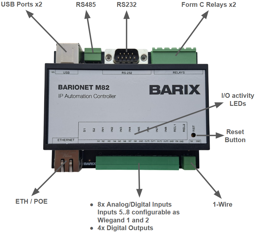
2. Hardware Functionality
USB ports x2
Two USB 2.0 Host (Type A) ports. Use these to connect optional USB compatible accessories like the Barionet UX8 I/O extension.
The USB ports are disabled by default when no USB extension is detected at start-up. A Flexa application must enable USB before a USB peripheral can be used, and an extension is only detected if it is present at boot.
RS-232 Serial interface (DB9 connector)
-
RS-232 output levels: ±5 V to ±7 V (internally generated)
-
RS-232 input tolerance: up to ±15 V
-
Device node for applications:
/dev/ttyS1
|
pin# |
description |
|---|---|
|
1 |
NC |
|
2 |
RxD - Receive Data |
|
3 |
TxD - Transmit Data |
|
4 |
NC |
|
5 |
GND |
|
6 |
NC |
|
7 |
RTS - Request To Send |
|
8 |
CTS - Clear To Send |
|
9 |
NC |
RS-485 Serial interface (terminal block)
Half-duplex 2-wire RS-485 on a dedicated terminal block. The transmit driver is enabled automatically while sending. On-board termination is selectable with a jumper - enable it only on the two devices at the physical ends of the bus. Device node for applications: /dev/ttyS2.
|
pin# |
Name |
description |
|---|---|---|
|
1 |
B (D-) |
RS-485 B / D- (inverting) |
|
2 |
A (D+) |
RS-485 A / D+ (non-inverting) |
|
3 (closest to USB) |
GND |
Signal ground / common reference |
Wiegand interfaces (using inputs 5..8)
The M82 provides two independent Wiegand card-reader interfaces. Their data lines share universal input terminals 5-8 - the readers do not have their own terminals:
|
Reader |
Data 0 |
Data 1 |
Device node |
|---|---|---|---|
|
Wiegand 1 |
Input 5 |
Input 6 |
|
|
Wiegand 2 |
Input 7 |
Input 8 |
|
Power the reader from its own external supply (typically 12 V) and tie its ground to the Barionet ground; only the two data lines go to the Barionet.
Function LEDs (12 multicolor status indicators)
|
LED |
meaning |
|---|---|
|
S1 System status LED |
RED blinking: Startup.
|
|
S2 I/O Application status LED |
The firmware sets this LED RED when the application service starts or stops; it does not turn it green automatically. It is intended to be driven by the application to signal its own state (for example GREEN when the app is up and healthy). An application that does not set this LED leaves it RED even while running - so a solid RED here does not by itself mean that no application is running. |
|
IN1 .. IN8 Input LEDs |
The colour reflects how the terminal is being read:
|
|
REL1 .. REL2 Relay LEDs |
GREEN solid: Relay is activated.
|
The 4 digital outputs (OUT0..OUT3) do not have front-panel indicator LEDs.
Reset button
Use a pointed tool to press this button and perform a "Reboot" or "Reset to Factory Defaults". See Section 9 for the full explanation.
16-pin screw terminal block
Use the supplied 16-pin female terminal block to make the input, output and power connections (if external PSU is used).
-
8 analog/digital inputs with configurable pull-ups (0-15 V)
-
4 digital (solid-state) outputs
-
External power supply 9..30 VDC
|
pin# |
Name |
description |
|---|---|---|
|
1 |
IN1 |
Digital/Analog Input #1 |
|
2 |
IN2 |
Digital/Analog Input #2 |
|
3 |
IN3 |
Digital/Analog Input #3 |
|
4 |
IN4 |
Digital/Analog Input #4 |
|
5 |
IN5 |
Digital/Analog Input #5 (also Wiegand 1 D0) |
|
6 |
IN6 |
Digital/Analog Input #6 (also Wiegand 1 D1) |
|
7 |
IN7 |
Digital/Analog Input #7 (also Wiegand 2 D0) |
|
8 |
IN8 |
Digital/Analog Input #8 (also Wiegand 2 D1) |
|
9 |
GND |
Ground |
|
10 |
OUT0 |
Digital output #1 |
|
11 |
OUT1 |
Digital output #2 |
|
12 |
OUT2 |
Digital output #3 |
|
13 |
OUT3 |
Digital output #4 |
|
14 |
GND |
Ground |
|
15 |
VIN |
9..30 VDC (positive) |
|
16 |
GND |
Negative |
The digital outputs are solid-state, open-drain low-side switches: when active they connect the output terminal to ground. Wire the load between an external positive supply and the output terminal, and tie that supply's 0 V to the Barionet ground.
6-pin screw terminal block (relays)
-
2 Form C (SPDT / changeover) relay outputs, rated 1 A @ 30 VDC
|
pin# |
Name |
description |
|---|---|---|
|
1 |
CM1 |
Relay #1 Common |
|
2 |
NC1 |
Relay #1 Normally Closed |
|
3 |
NO1 |
Relay #1 Normally Open |
|
4 |
CM2 |
Relay #2 Common |
|
5 |
NC2 |
Relay #2 Normally Closed |
|
6 |
NO2 (closest to RS232) |
Relay #2 Normally Open |
The relay contacts are dry (potential-free) and isolated from the device electronics - supply your own switched voltage.
1-Wire (2-pin terminal block)
Connect 1-Wire temperature sensors. Up to 50 sensors can be connected on the 1-Wire bus (wired in parallel on the same two terminals). Tested with the DS18B20 sensor family. The bus pull-up resistor is on the board, so no external resistor is needed.
|
pin# |
description |
|---|---|
|
1 |
1-Wire |
|
2 |
GND |
Ethernet / PoE (RJ45)
Ethernet 10/100 Mbps port with support for the IEEE 802.3af PoE standard.
3. Device Mounting
Slide the device upwards onto the DIN rail. Push it up and towards the rail until it snaps onto the upper rail edge.
Before powering the unit, please read this Quick Installation Guide.
4. Connecting power
You can power the Barionet M82 device using a power supply or PoE:
-
Using a Power Supply. Use pins 15-16 on the 16-way terminal block to connect a DC voltage power source of 9..30 VDC to the power input. The device draws max. 4 W with no USB peripherals connected. Polarity matters - ensure correct connection with the PSU (pin 15 positive, pin 16 negative).
-
Using PoE (Power over Ethernet). The Barionet M82 can also be powered by PoE supporting the IEEE 802.3af standard. Simply connect a LAN cable from a PoE-capable network switch to the unit's Ethernet plug.
When powered up, the CPU Status LED will start blinking, indicating that the device is starting up.
5. Connecting via Ethernet
Plug an Ethernet cable from your network switch to the Barionet M82.
The Barionet M82 is configured to be a DHCP client by default. Check the DHCP lease table of your DHCP server to retrieve the assigned IP address according to the given MAC address. Note the IP address.
You can also use the Barix "Discovery Tool" (see the next chapter) to find the device IP address.
6. Using the Barix Discovery Tool
The Barix Discovery Tool is a convenient Java-based application designed to locate Barix devices on your local network. It allows you to identify the IP address of any Barix device using its MAC address, which can be found on the back of the device. The tool can also detect devices with incorrect or missing IP configurations and enables you to set their IP address.
Prerequisites:
-
Java Runtime Environment (JRE) must be installed.
-
Ensure that the Windows firewall does not block traffic (UDP port 30718).
-
Compatible with Barix devices running firmware from 2012 or later.
-
Only detects Barix devices within the same local LAN.
Download the Discovery Tool and instructions from this page.
7. Configuration
The M82 can be configured using the Web Interface. Use your web browser in order to connect to the determined IP address as described:
-
Open your browser.
-
In the address bar, type:
<http://<IP> address>/where<IP address>is the IP address you retrieved previously.
For example, if your Barionet is assigned to IP address 192.168.0.6, enter the following in the address bar: http://192.168.0.6/
Your browser will display the Barionet M82 login page.
Enter your Password information, which can be found on a sticker on the backside of the device. The access is performed over an HTTP connection by default. (user is “admin”)
Barix highly recommends securing your device with a strong password to protect access to the web configuration interface. It is possible to change the default password in the SETTINGS → SECURITY section of the web interface.
After signing in, the Barionet M82 Web Interface offers the following sections: Settings, SNMP, Status, Logs, Defaults, Update and Reboot.
The Barionet M82 is based on Barix's Flexa technology, which offers the possibility to build and deploy custom applications on top of the base firmware (see Section 10).
8. Firmware Update
Barix constantly releases firmware to keep up to date with security standards, add new features and fix bugs. Make sure to check for new firmware available at this link.
-
Download the latest update package for your device to your local drive. The package is delivered as a
.tarfile. Please make sure you are downloading the right firmware for the Barionet M82. -
Check the current version on the Barionet M82 device. The easiest way to do this is to use the Web Interface. Go to the "Update" tab; under "Firmware" you can find the information about the current firmware version.
-
Click the link: "Please click here to start update". You enter the System Update page.
-
Click on "Choose file".
-
Change the current directory of your local drive to the folder where you downloaded the update
.tarfile and select it (do not untar the file or extract the archive). -
Click on "Upload".
-
The update will begin after loading. Please be patient during the update and do not disconnect the power supply. The software update can take several minutes. Once the update process has finished successfully the device will reboot and the new firmware will be started.
9. Reboot and Reset Factory Defaults
Reboot
-
Using the Reset button: press the "RESET" button for 3..5 s.
-
Using the Web Interface:
-
Go to the "Reboot" tab.
-
Press the "Reboot the device" button.
-
The "Reboot the device" button will be grayed out if the "Reboot" function is disabled from the Security Settings page.
Reset to Factory Defaults
-
Using the Reset button (full reset): a local user can completely reset the device to factory defaults (Hardware Reset) including network settings. Press the RESET button for approximately 10 seconds using a pointed tool. The device will reboot and apply default settings.
-
Using the Web Interface (partial reset):
-
Go to the "Defaults" tab.
-
Click on "Reset factory defaults" to revert all settings except "Network settings" to the factory defaults.
-
When the message "Settings successfully reverted to factory defaults." appears, the procedure is completed.
-
The "Reset factory defaults" button will be grayed out if the "Reset factory defaults" function is disabled from the Security Settings page.
Any reset-to-defaults mechanism removes any loaded application from the unit.
10. Upload your Flexa applications
The Barionet M82 provides a robust development environment for creating custom applications, leveraging the flexible architecture of the Flexa Firmware platform. This capability represents one of the core strengths of the Barionet system, enabling users to extend functionality beyond standard operations.
Applications for the Barionet M82 can be written in C++, Lua or Python. Many examples can be found at https://help.barix.com/barionet/flexa-apps
Barix also provides a Claude AI "skill" that guides you through building a complete Barionet Flexa application from a plain-language description - see Your Own Flexa Application for Barionet with Claude AI.
Important Notice
The example applications provided are intended solely for educational and reference purposes. While Barix develops and maintains these examples, they are offered without warranty or support obligations. Users are responsible for adapting, testing, and securing any code for their specific production environments. Barix is not responsible for any Flexa application installed on the device - whether developed by the customer, by a third party, or generated with the assistance of a tool such as the Claude AI skill - nor for any harm it may cause or any security weakness it may introduce.
11. Compliance and further Information
This equipment has been tested and found to comply with the limits for a Class B digital device, pursuant to part 15 of the FCC Rules. These limits are designed to provide reasonable protection against harmful interference in a residential installation. This equipment generates, uses and can radiate radio frequency energy and, if not installed and used in accordance with the instructions, may cause harmful interference to radio communications. However, there is no guarantee that interference will not occur in a particular installation. If this equipment does cause harmful interference to radio or television reception, which can be determined by turning the equipment off and on, the user is encouraged to try to correct the interference by one or more of the following measures:
-
Reorient or relocate the receiving antenna.
-
Increase the separation between the equipment and receiver.
-
Connect the device into an outlet on a circuit different from that to which the receiver is connected.
-
Consult the dealer or an experienced radio/TV technician for help.
Safety and precaution recommendations apply. Find them in the download section at http://www.barix.com
Find your distributor on this list for more hardware.
For questions that extend the documentation, feel free to contact us on:
International: +41 434 33 22 22
USA: +1 866 815 0866
Email: support@barix.com
All information and the use of this product including all services are covered under the Barix Terms & Conditions and our Privacy Policy. Please follow the Safety and Precaution Recommendations. Barix is an ISO 9001:2015 certified company. All rights reserved. All information is subject to change without notice. All mentioned trademarks belong to their respective owners and are used for reference only.