
Introduction
What is Barionet?
The Barionet family from Barix represents a comprehensive line of programmable, network-enabled automation controllers designed to bridge the gap between traditional devices and modern IP-based networks in both residential and industrial automation environments. These versatile controllers enable virtually any device to become network-accessible, allowing for seamless monitoring and control through industry-standard protocols including SNMP, UDP, TCP, MQTT, and many others.
Each Barionet device features a robust combination of hardware and software interfaces, complemented by general-purpose inputs and outputs that support a wide range of control and monitoring applications. This flexibility makes Barionet controllers ideal for system integrators and installers seeking reliable, feature-rich automation solutions.
Barionet Product Categories
The Barionet family consists of three distinct product categories, each built on different technological foundations:
1. Legacy Barionets
-
Barionet 50
-
Barionet 100
2. Linux OpenWrt (Qino) Based Barionets
-
Barionet 400
-
Barionet 1000
3. Linux Yocto (IPAM400) Based Barionets
-
Barionet M44 (covered in this manual)
-
Barionet M82 (covered in this manual)
About the Barionets Covered in This Manual
Important: This manual focuses on the IPAM-Yocto-based Barionet M44 and Barionet M82 and their specific features and capabilities. The two devices share the same Flexa firmware platform and development model; they differ in the number and type of physical I/O, which is called out throughout the manual.
Barionet M44
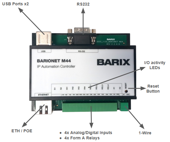
The Barionet M44 delivers exceptional versatility through its comprehensive array of physical interfaces:
Input/Output Capabilities:
-
4× Digital/Analog Inputs with configurable pull-up resistors
-
4× Form A (Normally Open) relay outputs
-
1× RS-232 serial communication port
-
2× USB 2.0 ports for peripheral connectivity
-
1× 1-Wire interface with native temperature sensor support
-
2 front-panel user LEDs controllable from an application
Expandability:
-
Compatible with Barionet UX8 I/O expansion modules via USB connection for additional input/output capacity
Network Connectivity:
-
1× 10/100 Mbps Ethernet port with integrated Power over Ethernet (PoE) support (IEEE 802.3af compliant)
Barionet M82
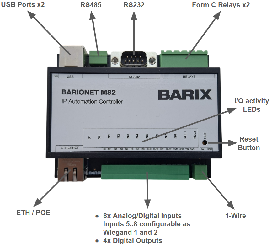
The Barionet M82 is the higher-density member of the Yocto-based family. It runs the same Flexa firmware and is programmed the same way as the M44, but offers more I/O and two additional interface types:
Input/Output Capabilities:
-
8× Digital/Analog Inputs with configurable pull-up resistors
-
4× Digital (solid-state) outputs
-
2× Form C (changeover / SPDT) relay outputs
-
2× RS-232/RS-485 serial communication ports (the second port includes a transmit-enable line for half-duplex buses)
-
2× Wiegand card-reader interfaces (sharing input terminals 5–8)
-
2× USB 2.0 ports for peripheral connectivity
-
1× 1-Wire interface with native temperature sensor support
Expandability:
-
Compatible with Barionet UX8 I/O expansion modules via USB connection
Network Connectivity:
-
1× 10/100 Mbps Ethernet port with integrated Power over Ethernet (PoE) support (IEEE 802.3af compliant)
The below table shows a quick comparison between Barionet M44 and Barionet M82:
|
Interface |
Barionet M44 |
Barionet M82 |
|
Relays |
4 × Form A (NO) |
2 × Form C (changeover / SPDT) |
|
Digital outputs (solid-state) |
— |
4 |
|
Universal input terminals (digital / analog ) |
4 |
8 |
|
Configurable input pull-ups |
4 |
8 |
|
Serial ports |
1 × RS-232 |
2 (RS-232 / RS-485) |
|
Wiegand readers |
— |
2 (on input terminals 5–8) |
|
1-Wire temperature sensors |
up to 50 |
up to 50 |
|
Front-panel user LEDs (app-controllable) |
2 |
— |
|
USB host ports |
2 |
2 |
|
UX8 expansion units |
up to 4 |
up to 4 |
|
Ethernet |
10/100 + PoE |
10/100 + PoE |
Flexa Firmware Platform
Both Barionets operate on Barix's advanced "Flexa" firmware platform, a sophisticated development environment that empowers users to create custom applications tailored to their specific integration requirements. This platform facilitates seamless connectivity with systems requiring specialized protocols, including but not limited to:
-
MQTT (Message Queuing Telemetry Transport)
-
HTTP/HTTPS (Hypertext Transfer Protocol)
-
TCP/UDP (Transmission Control Protocol/User Datagram Protocol)
-
Modbus RTU/TCP
-
BACnet (Building Automation and Control Network)
The Flexa platform's extensive library support ensures that higher-level applications can access virtually unlimited integration possibilities, enabling the Barionet to communicate effectively with diverse automation systems and protocols. This architectural approach provides installers and system integrators with the flexibility to adapt the device to meet specific project requirements while maintaining reliable, standards-based communication.
Barionet Applications
The versatility of the Barionet enables implementation across a wide spectrum of applications, limited only by your specific requirements and creative vision. The following examples demonstrate common deployment scenarios:
Industrial Control and Monitoring
Deploy the Barionet for comprehensive temperature and voltage monitoring in industrial environments. The device can automatically generate alarm notifications via email and/or SNMP when monitored parameters exceed predetermined thresholds, ensuring rapid response to critical conditions.
Home Automation Systems
Create sophisticated residential automation solutions by controlling thermostats, lighting systems, and other connected devices. The web-based interface enables convenient remote status monitoring and control from anywhere with internet access.
Legacy Device Integration
Transform older equipment with RS-232/RS-485 or Modbus interfaces into network-accessible devices. The Barionet serves as an intelligent serial gateway, allowing TCP/IP network control of traditional serial devices without requiring hardware modifications.
Access Control and Security
Implement robust security systems using relay outputs to drive audible alarms, warning lights, or access-control mechanisms. On the Barionet M82, the two built-in Wiegand reader interfaces make it a natural fit for badge/card access control. Integration with email and SNMP notification systems ensures immediate alert distribution when security events occur.
Remote Data Collection
Establish comprehensive data logging systems for both digital and analog inputs, enabling long-term trend analysis and remote monitoring of critical parameters.
MQTT-Based IoT Applications
Develop real-time control and monitoring solutions using MQTT protocol integration, perfect for Internet of Things (IoT) applications requiring low-latency communication and efficient data distribution.
Development Resources
Programming applications for the Flexa platform is straightforward, using familiar scripting languages such as Python and Lua; performance-critical apps can also be written in C/C++ or Rust. This accessibility allows both experienced developers and automation technicians to create custom solutions efficiently. The complete developer reference — I/O address maps, the io-mapping API, configuration options and packaging — is in the "Developing Flexa Applications" part of this manual.
Getting Started: Comprehensive example applications and development resources are available at: https://help.barix.com/barionet/flexa-apps. Barix also provides a Claude AI "skill" that guides you through building a complete Barionet Flexa application from a plain-language description — see Your Own Flexa Application for Barionet with Claude AI.
The combination of powerful hardware capabilities, a flexible software platform, and extensive development resources ensures that the Barionet can adapt to meet virtually any automation challenge you encounter.
About This Manual
This manual serves as a comprehensive resource for Barionet M44 and M82 users, system integrators, and application developers. The content is structured to accommodate varying levels of technical expertise while providing the detailed information necessary for successful implementation. It consolidates the material previously spread across the online Barionet for-developers pages into a single reference.
Prerequisites and Technical Requirements
Hardware Interface Knowledge: The hardware interfaces chapter assumes familiarity with basic electronics principles, including understanding of digital and analog signals, relay operation, and serial communication concepts.
Software Interface Knowledge: The software interface sections require some background knowledge of common internet protocols. Familiarity with network configuration principles will enhance your ability to implement advanced features.
Skill Level Considerations: While the Barionet can be deployed in basic configurations without extensive technical background, more complex implementations involving external device integration and custom application development may require additional expertise in electronics and software programming.
Technical Support Resources
Barix is dedicated to ensuring your success with the Barionet platform. Beyond this manual, we provide comprehensive technical resources including:
-
Online documentation and knowledge base: https://help.barix.com/barionet/
-
Example applications and code samples: https://help.barix.com/barionet/flexa-apps
-
Technical support services: email us at support[at]barix.com
Our commitment extends to helping both newcomers and experienced professionals achieve their automation objectives efficiently and effectively.
Interface Electrical Ratings
This chapter gives the electrical ratings and wiring guidance for the field interfaces on the Barionet M44 and M82: the universal (digital / analog) inputs, the digital outputs, the relay outputs, the RS-232 and RS-485 serial ports, and the power input and supply measurement. It is intended to let you connect field wiring safely and know what to expect; always keep within the limits below.
Universal digital / analog inputs
Each universal input terminal can be used as a digital input, an analog voltage input, or an edge counter, and has a software-switchable pull-up. The Barionet M44 has four (IN1–IN4); the Barionet M82 has eight (IN1–IN8). All channels are identical.
|
Rating |
Value |
|---|---|
|
Channels |
M44: 4 (IN1–IN4); M82: 8 (IN1–IN8) |
|
Input voltage range |
0–15 V DC (referenced to GND); do not apply negative voltages |
|
Analog reading |
Reported in millivolts over the full 0–15 V range (I/O address 501+) |
|
Input impedance |
≈100 kΩ to ground |
|
Digital sensing |
Suitable for dry (voltage-free) contacts with the pull-up enabled, or for a logic/voltage source within the 0–15 V range |
|
Pull-up |
Software-switchable per channel (I/O address 301+), on by default. Enable it for a dry contact; disable it for an analog source so the input does not load the signal. |
|
Counter |
Counts input transitions per channel (I/O address 401+) |
|
Protection |
Each input is transient- (surge-) protected and RF-filtered |
Wiring an analog input (Barionet M44 / M82) - two examples
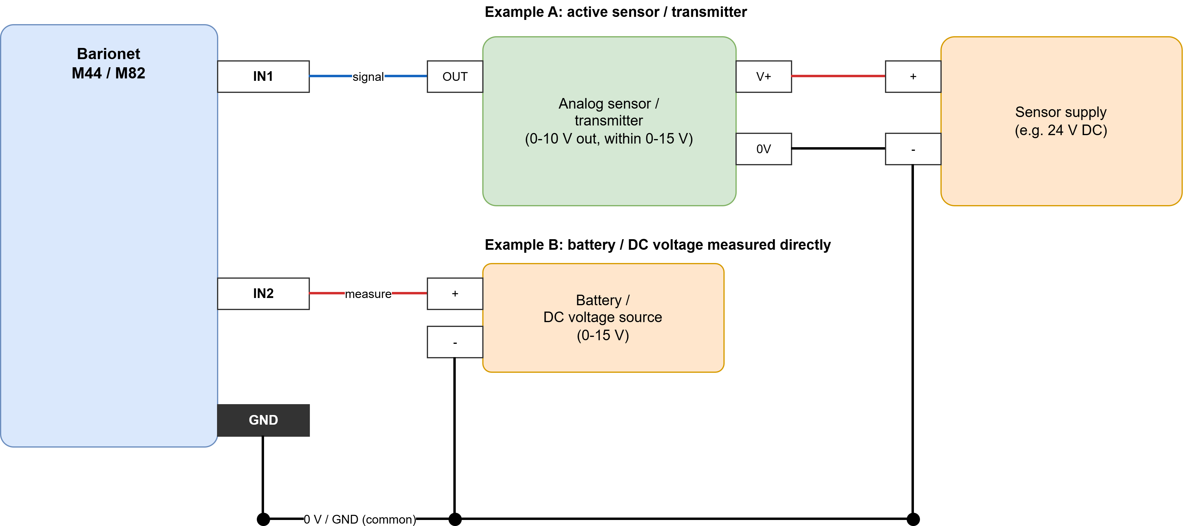
Notes (both examples)
-
Set the input pull-up OFF (register 301+) so it does not load the source. Read the value in millivolts
at address 501+ (IN1 = 501, IN2 = 502, ...). Input impedance approx 100 kohm. -
Example A - active sensor: signal -> IN, sensor 0 V -> Barionet GND, power the sensor from its own supply.
-
Example B - battery / DC source: connect + to the input and - to GND; the voltage is read directly, up to 15 V.
The battery negative becomes common with the Barionet GND - make sure that is acceptable in your circuit. -
Above 15 V (e.g. a 24 V battery) fit an external resistor divider to bring it under 15 V and scale in software.
-
4-20 mA sensor: fit a 250 ohm resistor from IN to GND (1-5 V). Potentiometer: ends across a reference and GND, wiper -> IN.
Wiring a digital input (Barionet M44 / M82)
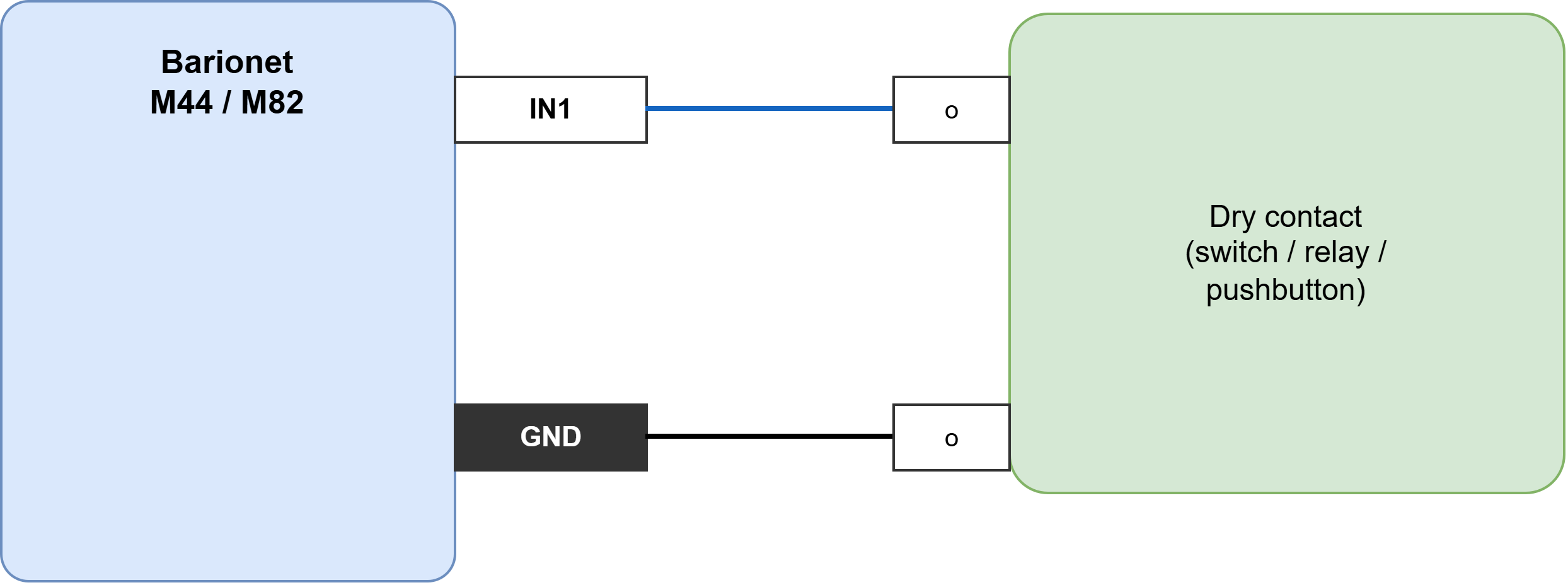
Notes
-
Enable the input pull-up (register 301+, ON by default): a closed contact reads 1 at address 201+.
-
The contact is voltage-free - just wire it between IN and GND. No external supply needed.
-
Powered sensor (NPN / open-collector): sensor output -> IN, sensor 0 V -> GND, power the sensor
externally, keep pull-up ON. PNP / push-pull output must stay within 0-15 V. -
The same terminal is also the analog input and counter for that channel (one terminal, not three).
Digital (solid-state) outputs
The Barionet M82 has four solid-state digital outputs (OUT0–OUT3); the Barionet M44 has none.
|
Rating |
Value |
|---|---|
|
Channels |
M82: 4 (OUT0–OUT3); M44: none |
|
Output type |
Open-drain, low-side switch: when active the output connects the load to ground (0 V). It cannot source current. |
|
Wiring |
Connect the load between an external positive supply and the output terminal; the output switches the low side. There is no internal pull-up. |
|
Max load supply voltage |
60 V DC (the external supply the load returns to) |
|
Max continuous sink current |
1.1 A per output |
|
Built-in protection |
Each output is self-protected against short circuit, over-current, over-temperature and over-voltage, and recovers automatically once the fault clears — suitable for inductive and lamp loads with high inrush |
|
Timed pulse |
Can be pulsed for a set time by the on-board timer (100 ms resolution), released automatically even if the application stops — see the "Developing Flexa Applications" part |
Wiring a load on a Barionet M82 digital output
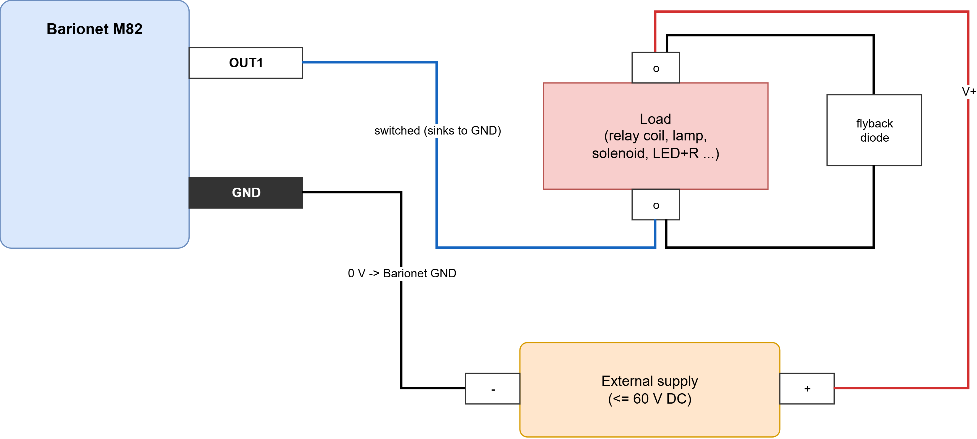
Notes
-
Open-drain, low-side switch: when ON it connects the OUT terminal to 0 V (GND). It cannot source current.
Wire the load between your external + supply and the OUT terminal. -
Tie the external supply 0 V to the Barionet GND (common return).
-
Max load supply 60 V DC, up to 1.1 A sink per output; self-protected (short / over-current / thermal).
-
Inductive load (relay/solenoid): fit a flyback diode across the load (cathode to +) as shown.
-
Outputs OUT1-OUT4; each supports the hardware timed pulse.
Relay outputs
Both models provide isolated, voltage-free (dry) relay contacts on a pluggable screw terminal. The relays can, like the digital outputs, be driven with the on-board timed pulse.
|
Rating |
Barionet M44 |
Barionet M82 |
|---|---|---|
|
Relays |
4 |
2 |
|
Contact form |
Form A (normally-open): common (CM) and normally-open (NO) per relay |
Form C (SPDT changeover): common (CM), normally-open (NO) and normally-closed (NC) per relay |
|
Terminals |
CM1/NO1 … CM4/NO4 (on the same terminal block as inputs IN1–IN4) |
CM1/NO1/NC1 and CM2/NO2/NC2 (dedicated relay terminal block) |
On both models the contacts are dry, potential-free and isolated from the device electronics — supply your own switched voltage. Both use the same relay type, so the contact ratings below apply to the M44 and the M82 alike:
|
Contact rating |
Value |
|---|---|
|
Max switching voltage |
125 V AC / 60 V DC |
|
Max switching current |
2 A |
|
Max switching power |
62.5 VA / 30 W |
|
Rated load (resistive) |
0.5 A at 125 V AC; 1 A at 30 V DC |
|
Minimum load |
1 mA at 5 V DC (gold-plated AgNi contacts, suitable for low-level signals) |
Stay within these limits and derate for inductive loads; confirm against the relay datasheet for demanding applications.
Wiring a load on a Barionet M44 relay (Form A, N/O)
.drawio.png?cb=eb4afd152bb041c1f42a54817923fdbb)
Notes
-
Form A = one N/O contact per relay: CM (common) and NO. Closed only while the relay is energised (ON).
-
Dry / potential-free contact: put it in series with YOUR supply and the load, as shown.
-
Max ratings (per relay): 2 A, 125 V AC / 60 V DC, 62.5 VA / 30 W. Resistive: 0.5 A @125 V AC, 1 A @30 V DC.
-
Inductive DC load: add a flyback diode across the load; AC: add an RC snubber. Derate for inrush.
-
Four relays: CM1/NO1 ... CM4/NO4.
Wiring a load on a Barionet M82 relay (Form C, changeover / SPDT)
.drawio.png?cb=1b8102f799f81ab439a21387fa51dc76)
Notes
-
Form C = changeover per relay: CM (common), NO, NC. CM-NO closed when energised (ON); CM-NC closed. When de-energised / powered off. Use NC for fail-safe outputs. Two relays: CM1/NO1/NC1 and CM2/NO2/NC2.
-
Dry / potential-free contacts - provide your own supply and load.
-
Max ratings (per relay): 2 A, 125 V AC / 60 V DC, 62.5 VA / 30 W. Resistive: 0.5 A @125 V AC, 1 A @30 V DC.
-
Add a flyback diode (DC) or RC snubber (AC) for inductive loads.
RS-232 serial port
Both models provide an RS-232 port (the first serial port, /dev/ttyS1).
|
Rating |
Value |
|---|---|
|
Standard |
True EIA/TIA-232 signal levels |
|
Max data rate |
Up to 120 kbps (covers all standard baud rates up to 115200 bps) |
|
Signals |
TX, RX, RTS, CTS — hardware (RTS/CTS) flow control is available (RTS at I/O address 9, CTS at 209) |
|
Connector |
9-pin D-sub (DE-9) |
|
Protection |
Signal lines are transient- (ESD/surge-) protected |
RS-485 serial port
The Barionet M82 provides a second serial port wired as RS-485 (/dev/ttyS2); the Barionet M44 does not have this port.
|
Rating |
Value |
|---|---|
|
Standard |
True EIA/TIA-485 (RS-485/RS-422), half-duplex (2-wire, A/B differential pair plus ground) |
|
Max data rate |
Up to 12 Mbps |
|
Bus nodes |
Up to 32 transceivers on the bus (standard unit load) |
|
Common-mode input range |
−7 V to +12 V |
|
Receiver fail-safe |
Reads a defined logic-high when the bus is idle, open or shorted |
|
Direction control |
Transmit is enabled by a transmit-enable line, available to applications as /dev/serial1Tx; the application asserts it while sending |
|
Termination |
100 Ω on-board termination, selectable with a jumper — enable it only on the two devices at the physical ends of the bus |
|
Connector |
3-pole 3.5 mm terminal: A (RS485_P), B (RS485_N) and ground |
|
Protection |
±15 kV ESD (Human Body Model) on the A/B line pins; driver short-circuit and thermal-overload protected; common-mode choke for noise rejection |
Wiring the RS-485 port (Barionet M82)
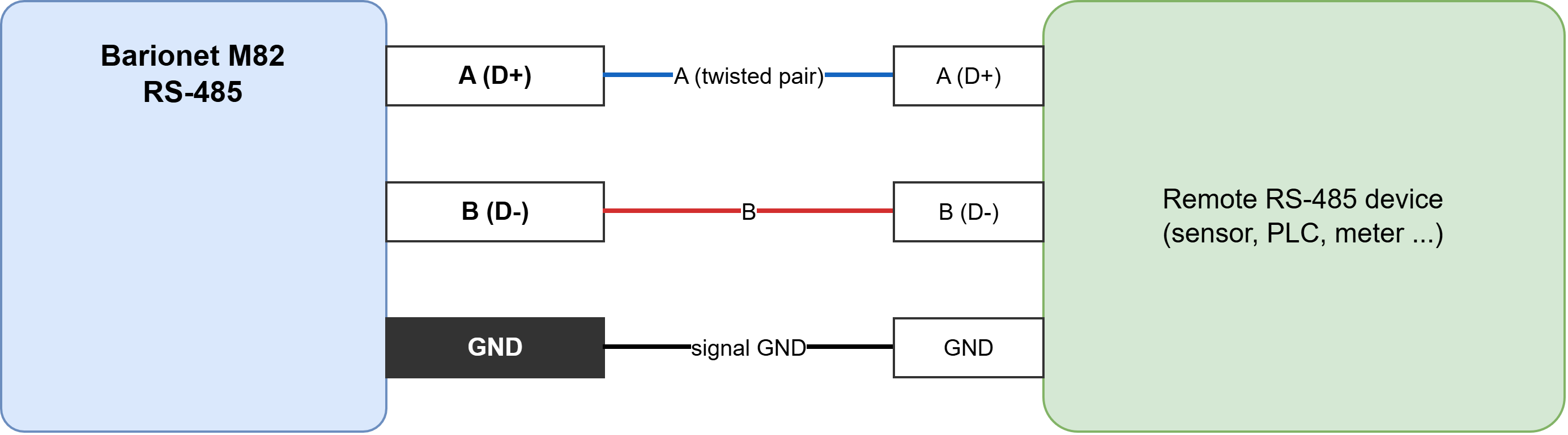
Notes
-
Half-duplex 2-wire bus: A(D+)->A, B(D-)->B on every device; keep A/B as a twisted pair.
-
Connect a signal-ground reference between devices (GND->GND) for reliable common-mode range (-7..+12 V).
-
Termination: enable the on-board jumper ONLY on the two devices at the physical ends of the bus.
-
Daisy-chain the bus (no long stubs / star). Up to 32 nodes, up to 12 Mbps.
-
The app raises the transmit-enable line while sending (/dev/serial1Tx); the port is /dev/ttyS2.
1-Wire temperature bus
Both models provide a 1-Wire (Dallas / Maxim) bus for digital temperature sensors. A single connector carries the whole bus, and every sensor is wired in parallel on it (DATA and GND). The bus pull-up resistor is already on the board (one shared pull-up for the entire bus) so no external resistor is fitted, and none is added per sensor. Sensors run in parasite-power mode, taking their power from the data line (their VDD tied to GND). Sensors are detected automatically and their readings appear directly in the I/O address map.
|
Rating |
Value |
|---|---|
|
Standard |
1-Wire (Dallas / Maxim), single-master |
|
Terminals |
2: DATA (DQ) and GND |
|
Bus pull-up |
On-board, approx. 2.2 kΩ — one shared pull-up for the whole bus (do not add an external or per-sensor resistor) |
|
Sensor power |
Parasite power (sensor VDD tied to GND; powered from the data line) |
|
Max sensors |
Up to 50 on the bus, each auto-discovered |
|
Reading (I/O map) |
Temperature in milli-°C at addresses 601+; 64-bit sensor ID at 651+; an empty slot reads the no-sensor value “4096” |
|
Recommended wiring |
One continuous run, short stubs; keep total bus length modest (tens of metres) |
Wiring 1-Wire temperature sensors
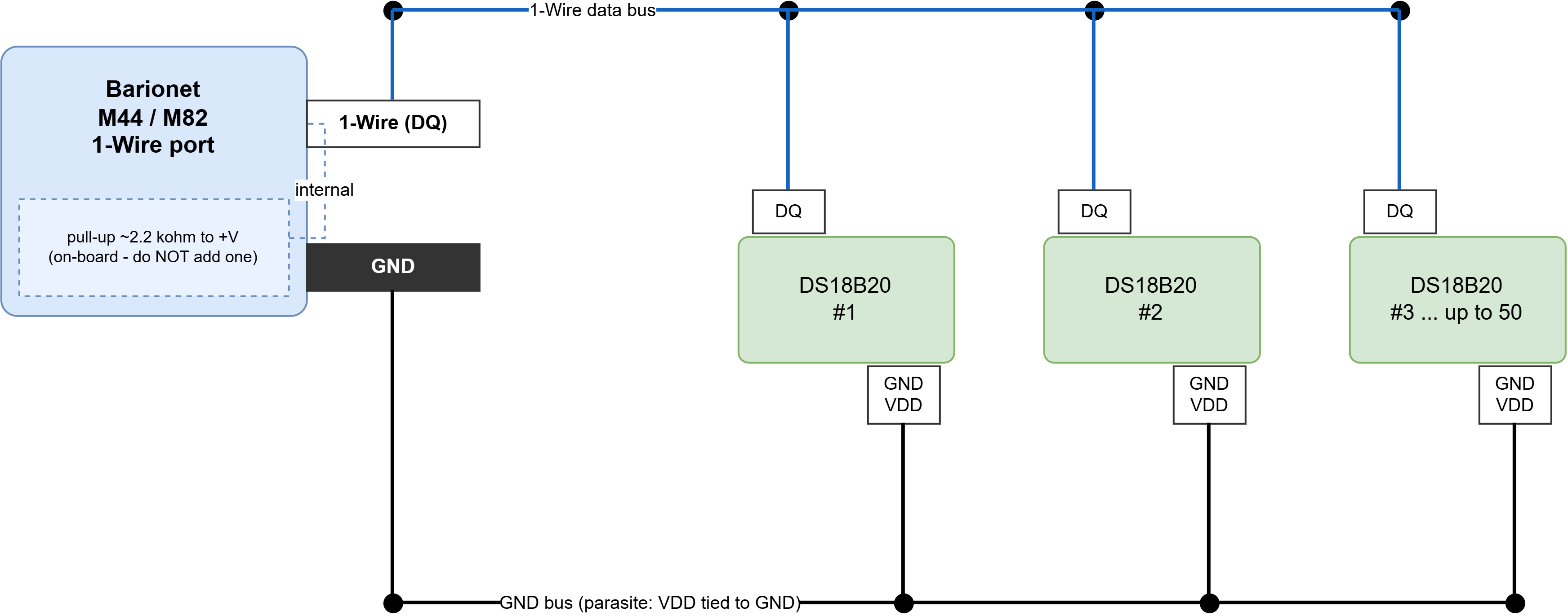
Notes
-
A pull-up resistor IS required on the data line, but only ONE for the whole bus - and it is already fitted on the Barionet (approx 2.2 kohm). Do NOT add an external resistor, and NOT one per sensor.
-
Connector = two terminals: DATA (DQ) and GND. Parasite power: on each DS18B20 tie VDD to GND.
-
Wire all sensors in parallel on the same two wires (bus / daisy-chain). Up to 50; each auto-discovered. Values (milli-deg C) at addresses 601+, unique IDs at 651+.
-
Keep the bus one continuous run (short stubs). Very long buses / many parasite sensors may need a stronger or active pull-up - never per-sensor resistors. 'DS1820B' = DS18B20 (or DS18S20 / DS1820).
Wiegand card-reader interfaces (Barionet M82 only)
The Barionet M82 provides two independent Wiegand interfaces (the M44 has none). Each reader's Data0 and Data1 lines connect to a pair of the universal input terminals (5-8); the M82 decodes Wiegand on those pins continuously and in hardware, from boot, in parallel with their normal digital-input function. The reader itself is powered from an external supply: only its two data lines and a common ground go to the Barionet.
|
Rating |
Value |
|---|---|
|
Channels |
2, independent (device nodes |
|
Data terminals |
Reader 1: D0 = input 5, D1 = input 6. Reader 2: D0 = input 7, D1 = input 8 |
|
Signal |
2-wire Wiegand (Data0 / Data1); each line uses the universal-input front end |
|
Data-line electrical |
0-15 V referenced to GND, approx. 100 kΩ; enable the input pull-ups (register 301+) on the reader lines |
|
Reader power |
External supply (typically 12 V) — NOT provided by the Barionet; tie the reader 0 V to the Barionet GND (common reference) |
|
Activation |
Always on from boot, decoded in hardware; no enable bit or mode setting |
|
Reader compatibility |
Standard Wiegand readers with frames up to 64 bits (e.g. 26/34/37-bit); the application selects and validates the frame length |
|
Shared function |
Terminals 5-8 remain digital inputs as well — do not also use them as plain contacts while a reader is wired |
Wiring a Wiegand card reader (Barionet M82)
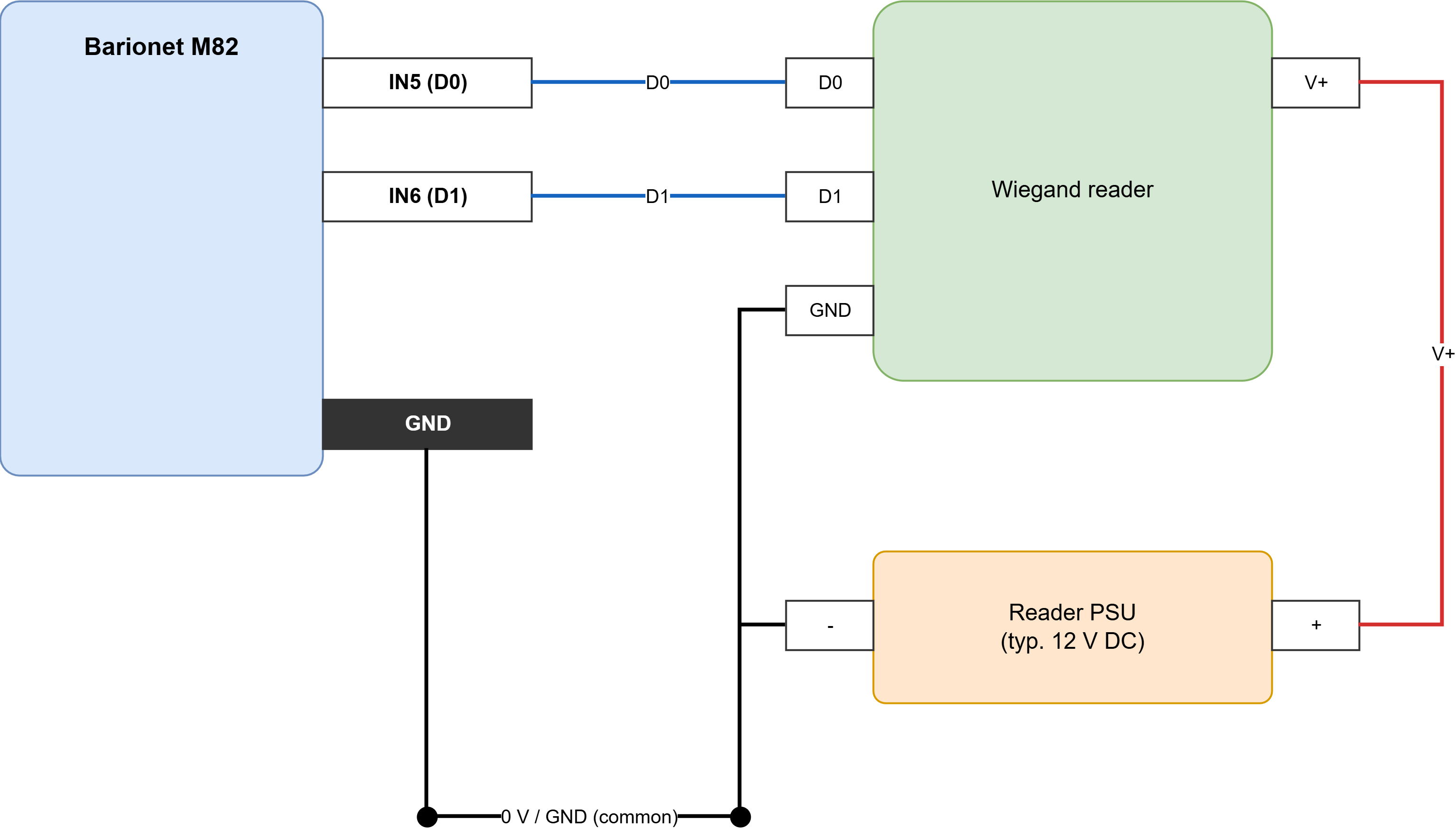
Notes
-
The reader is powered EXTERNALLY (usually 12 V). Only its data lines go to the Barionet.
-
Reader 1 -> /dev/wiegand0: D0 -> IN5, D1 -> IN6. Reader 2 -> /dev/wiegand1: D0 -> IN7, D1 -> IN8.
-
Tie the reader 0 V / PSU minus to the Barionet GND (common reference). Enable the pull-ups on those inputs.
-
Terminals 5-8 are always both plain inputs AND Wiegand data: do not also use them as contacts when a reader is wired, and have the app discard frames that are not a valid card length (e.g. 26-bit).
Power input and supply measurement
The device can be powered from an external DC supply or over Ethernet, and continuously measures its own supply voltage and current, which are readable from an application (I/O addresses 1201 and 1202) and shown on the Status page.
|
Rating |
Value |
|---|---|
|
DC input voltage |
9–30 V DC, on terminal pins 15 (+) and 16 (−); reverse-polarity protected |
|
Power over Ethernet |
IEEE 802.3af (PoE); used automatically when a DC supply is not present |
|
Power consumption |
12 W maximum (all relays active) |
|
Supply current reading |
Measured on-board, reported in milliamps (I/O address 1201) |
|
Supply voltage reading |
Measured on-board, reported in millivolts (I/O address 1202) |
UX8 I/O extension modules
The Barionet UX8 is a USB-connected I/O extension that adds eight relay outputs and eight inputs to a Barionet head unit. It is supported by both the Barionet M44 and the Barionet M82. Up to four UX8 units can be attached to one head unit, and their I/O appears in the same address map as the built-in I/O (see the "Developing Flexa Applications" part), so an application uses UX8 I/O exactly as it uses the on-board I/O.
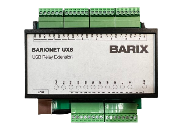
UX8 specifications
|
Rating |
Value |
|
Inputs |
8 × dry-contact inputs, 0–15 V (voltage-free contact closures); also readable as counters and analog values through the I/O address map |
|
Relays |
8 × Form C (SPDT changeover): common (CM), normally-open (NO) and normally-closed (NC) brought out per relay |
|
Relay maximum load |
1A @ 30VDC or 0.5A @ 125VAC |
|
Power |
Supplied by the Barionet head unit over the USB connection.
|
|
Connection |
USB Type-B "HOST" connector, cabled to a USB port on the Barionet |
|
Reset |
A reset button performs a hardware reset of the UX8's on-board microcontroller |
|
Units per head unit |
Up to 4 (on both the M44 and the M82) |
Connecting and addressing UX8 units
Each UX8 carries a two-position DIP switch (SW1) that sets its address, so the head unit can tell several modules apart. Give every attached UX8 a different address.
A single UX8: just connect the USB cable at both ends and power up the Barionet. One module uses the default Address #1 and needs no switch change.
Two or more UX8: before connecting them, open each case, set its DIP switch to a unique address as in the table below, close the case, connect all modules to the Barionet's USB ports, and then power up the Barionet.
|
UX8 address |
Switch 1 |
Switch 2 |
|
Address #1 |
OFF |
OFF |
|
Address #2 |
OFF |
ON |
|
Address #3 |
ON |
OFF |
|
Address #4 |
ON |
ON |
Addresses #1 and #2 are set exactly as shown in the Barix UX8 figures; addresses #3 and #4 follow the same pattern (the two switches encode the address in binary, with switch 2 as the least-significant bit), allowing up to four modules on one head unit.
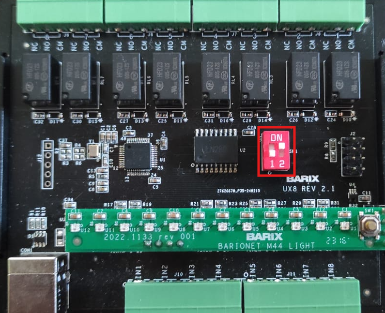
Important connection notes:
-
The Barionet's USB ports must be enabled for a UX8 to be detected (USB enable, I/O address 1207 — see the "Developing Flexa Applications" part).
-
A UX8 is detected at boot. Connect and address your UX8 modules before powering the Barionet; hot-plugging one afterwards requires a reboot before it is recognized.
-
Which UX8 units are present can be read at I/O addresses 60007–60010 (units 1–4), and their relays, inputs, counters and analog values occupy the UX8 ranges of the address map.
-
When connecting more than 2x UX8 to a single Barionet adopt an externally powered USB hub. Barionet USB port provide a limited amount of current (500mA) and can’t power more than 2 UX8 extensions. Keep USB cables as short as possible.
Accessing and Configuring the Barionet
The Barionet features an integrated web server with pre-loaded configuration pages that enable you to customize various device settings through an intuitive web interface. This chapter delivers comprehensive, step-by-step instructions for establishing your initial network connection and accessing the essential status and configuration pages during first-time setup. The web interface is identical on the Barionet M44 and M82; where a page reflects a hardware difference, it is noted.
Accessing the Barionet for the first time
Step 1: Connect to an Ethernet IP network
The first step in preparing to access the Barionet's configuration and status pages is to connect it to an Ethernet network and assign it an IP address. The Barionet is equipped with a standard Ethernet 10/100 Mbit, full/half duplex, auto-negotiation interface. Connect the Barionet to an Ethernet network using an RJ-45 Ethernet cable to a network switch. You'll also need a computer connected to the same network.
The Barionet operates as a DHCP client by default, requiring access to a reachable DHCP server for initial device communication. Once you successfully establish this initial connection, you can modify the unit's network settings to implement a static IP configuration if your network requirements demand it.
Connecting the Barionet directly to a PC will not establish communication since the device operates as a DHCP client by default and requires a DHCP server to obtain network configuration.
Step 2: Connect Power
Both the Barionet M44 and M82 support Power over Ethernet (IEEE 802.3af), enabling the device to receive power directly through the network cable. When connected to a PoE-enabled switch, the Barionet will automatically power on immediately upon establishing the network connection.
Alternatively, an external PSU (not included in the package) can be used: both models can be operated from any DC power supply with an output voltage between 9 and 30 volts DC, applied to the power input pins on the screw terminal block. PoE and an external supply may both be connected; PoE is used when available.
On both the Barionet M44 and the Barionet M82 the power input pins are pin 15 (+ positive) and pin 16 (- negative) on the 16-position screw terminal block. Ensure the polarity and the connection pins are correct to avoid damaging your device.
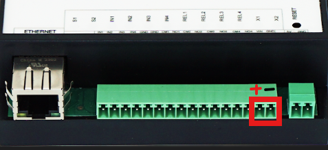
Step 3: Discover the Barionet on the network
Method 1: Using the Barix Discovery Tool
The Discovery Tool is available as a free download from https://help.barix.com/tools/discovery-tool.
Developed in Java, the Discovery Tool requires a Java Runtime Environment (JRE) to be installed on your system. If you lack a JRE installation, download and install it from: https://www.java.com/en/download/. Java runtime environments support most major operating systems. Linux and UNIX users should note that the Discovery Tool additionally requires the X-window graphical user interface to function properly.
The Discovery Tool comes packaged as a Java Archive (.jar) file. On most operating systems, you can launch the application by double-clicking the discover.jar file. Upon opening, the Discovery Tool displays the following interface:
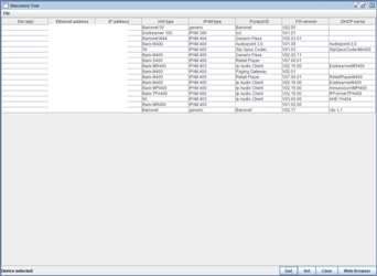
The Discovery Tool needs allowance through UDP port 30718 to operate correclty. Click the "Get" button to initiate the network scan. The program will search your network and display all discovered Barix devices along with their current IP addresses, MAC addresses (shown as "Ethernet Address" in the Discovery Tool), firmware versions, and additional device information. The Discovery Tool identifies any device residing on the same network segment as your computer, irrespective of their current IP address configurations. Note that the tool cannot search beyond routers to other subnets. Use the IP address displayed in the Discovery Tool to access your device through a web browser.
Setting a static IP Address using the Discovery Tool:
-
In the Discovery Tool window, double-click the IP Address field of the target device to configure its static IP address.
-
Enter your desired IP address assignment.
-
Click "SET" in the lower right corner—the tool will confirm success by displaying "No error" in the "Set reply" column.
-
Reboot your device and navigate to the web interface using the newly assigned IP address. Ensure you complete the network configuration by setting the subnet mask, gateway, and DNS parameters, as incomplete settings may cause operational issues.
The Discovery Tool does not provide options for configuring subnet mask, gateway, and DNS settings—these parameters must be entered manually through the device's web configuration interface.
Method 2: Using the device hostname
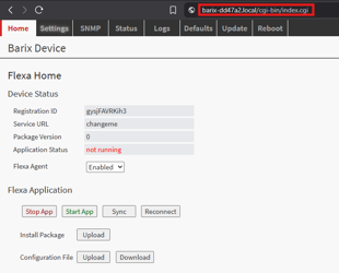
Every Barionet device ships with the Avahi zero-configuration service enabled by default. This feature provides the device with a discoverable hostname that resolves to an IP address within the local area network. This capability allows you to access the Barionet's web interface without needing to determine its IP address. Simply enter the following URL format in your browser: "http://barix-<MACLast6Digits>.local" (for example: "http://barix-09c2a1.local").
Method 3: Using the DHCP Lease table
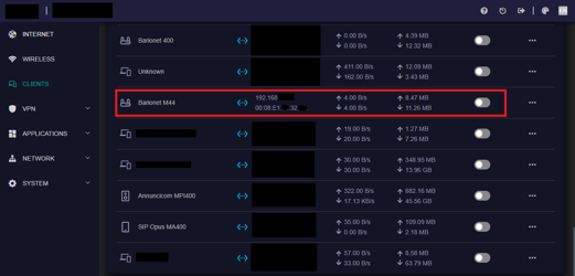
Most DHCP servers provide the ability to view a list of connected devices along with their assigned IP addresses and corresponding MAC addresses. In many cases, routers include a built-in DHCP server accessible through a web browser interface. This functionality simplifies the process of locating any device's IP address within the network served by that DHCP server. An example is shown below.
HINT: Any Barix device MAC Address starts with 00:08:e1
WHAT IF NO DHCP IS REACHABLE? When the device boots without access to a reachable DHCP server, the unit becomes unusable on the network. Under these conditions, it assigns itself the placeholder IP address 0.0.0.0, which prevents any network functionality. The boot process extends significantly during this scenario because the device makes multiple attempts to contact the DHCP server before proceeding with application execution.
The Web Configuration Interface
With the device's IP address, you can access the web configuration interface to manage various settings and parameters. This section describes each tab available within the web configuration interface, providing detailed guidance for navigating and utilizing these management options.
-
Open your web browser and enter the following in the address bar:
http://<IP Address>/ -
Replace
<IP Address>with your Barionet's actual IP address. For example, if your Barionet has been assigned IP address 192.168.0.6, enter:http://192.168.0.6 -
The login page appears, enter the credentials – user is admin and the password is unique for each device and printed on a sticker applied at the bottom of the unit
Keep your login credentials safe. After your first login, change the default password and do not share it with anyone outside intended operators or trusted personnel.
-
Your browser will then display the Barionet's HOME tab as illustrated below.
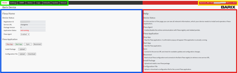
The web configuration is organized as follows:
|
|
Navigation Menu |
|
|
Product name, MAC address and current firmware version |
|
|
Operational Area |
|
|
Quick Help section |


In the following sections every tab displayed on the web UI is described in detail.
Home tab
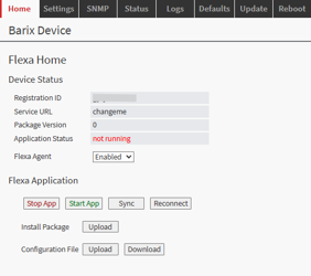
This tab displays essential information regarding the device's "Flexa" status. The concept operates straightforwardly: custom-developed applications run on the Flexa unit (the Barionet in this instance), where applications can be:
-
Retrieved from a service cloud portal, or
-
Installed through the local web configuration interface (Home tab).
This tab's purpose is to inform users about the current status of the loaded "Flexa Application." For more information about Flexa visit: Flexa User Manual — General Introduction.
|
Device Status |
Description |
|
RegID |
Unique alphanumeric identifier for every Barix device. Meaningful when the Flexa app is retrieved via the service portal. |
|
Service URL |
The URL endpoint given by the Flexa Registry to the device. |
|
Package Version |
The version of the package provided when installing the Flexa application. |
|
Application Status |
The current status of the Flexa Application. When loading such an application, a watchdog service initiates to control and monitor the application's operational status. |
|
Flexa Agent |
Enable/disable the online communication with the Flexa registry and the service portals. Default: Enabled. |
|
Flexa Application |
Description |
|
Start / Stop |
Control the Flexa Application to start or stop. |
|
Sync |
Forces the device to synchronize with the service portal. When an application is distributed through a service portal, the Barionet does not maintain a real-time connection with the portal. Consequently, any portal-side changes—whether configuration updates or application modifications—require device re-synchronization. This can be accomplished either by manually rebooting the unit or by pressing this button. |
|
Reconnect |
Resets the current Flexa configuration and connects to the Barix Flexa registry to retrieve a new service URL. |
|
Install Package |
Offers a way to install a Flexa Application without a service portal being involved. |
|
Configuration File |
Flexa Applications can expose configuration parameters through JSON configuration files that follow a specific object format. UPLOAD: uploads a new configuration file to the device. DOWNLOAD: retrieves the current configuration file in use. |
JSON configuration files are not the only method for configuring Flexa Applications. You can also utilize Barix's SDF (Settings Definition File) framework, which provides a way to declare web UI elements in a JSON file that will be displayed in a dedicated tab. Using SDF, you can display various interactive elements including text input fields, sliders, combo boxes, selectors, and additional controls, all organized within a dedicated web UI tab. This approach significantly enhances the user experience when configuring Flexa Applications. SDF is described in detail in the "Developing Flexa Applications" part of this manual.
Settings tab
This tab provides system settings configuration for managing Network Settings, Time Settings, and Security Settings. Click the corresponding accordion section to expand and access the configuration parameters for the desired setting.
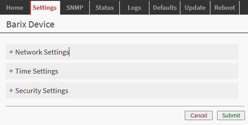
Network Settings
In this section, you can configure the network settings for the Barionet. You have the option to select between dynamic or static address assignment methods for the Ethernet interface.
The unit supports Dynamic Host Configuration Protocol (DHCP), which allows the device to obtain an IP address from a pool managed by a DHCP server. When the device connects to the network, the server assigns an available IP address from its pool. This address comes with an associated lease time, meaning that once the lease expires, the DHCP server may reassign that IP address to other network devices, potentially giving your device a different address upon renewal. Additionally, the DHCP server automatically provides all related network information to the requesting device, including subnet mask, gateway, and DNS server addresses.
While DHCP provides a convenient method for IP address assignment, certain situations require static IP addresses. In these instances, you can manually assign a static IP address to the Barionet device to ensure consistent network addressing over time.
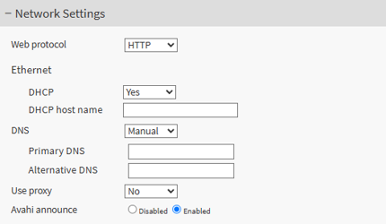
|
Parameter |
Description |
|
Web Protocol |
Specifies the protocol used to access the device's web configuration interface, choosing between HTTP or HTTPS. When set to HTTPS, you must enter the URL as https://IP_ADDRESS/. The Barionet includes a pre-loaded self-signed certificate; since browsers do not trust self-signed certificates, they display a security warning that requires user confirmation to proceed. 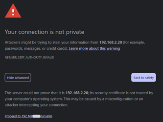
Clicking "Advanced" and then "Proceed to <IP_ADDRESS> (unsafe)" will access the web configuration interface. The communication between your browser and the device remains encrypted despite the warning.
|
|
DHCP |
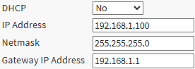
When set to "Yes" the device is a DHCP client and retrieves all required IP information from the DHCP server. When set to "No" it offers the parameters to assign a static IP address configuration — IP Address, Netmask, and Gateway IP Address. Default: Yes (DHCP Client mode).
|
|
DHCP Hostname |
A human-readable name that the device sends to the DHCP server when requesting an IP address, allowing the server to associate the assigned IP address with a meaningful name rather than just a MAC address. This makes it easier to identify devices in DHCP client lists, network monitoring tools, and router administration interfaces.
|
|
DNS |
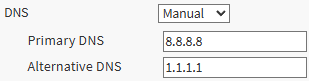
DNS (Domain Name System) translates human-readable domain names into IP addresses. Auto: the DNS entries are retrieved from the DHCP server (requires DHCP set to "Yes"). Manual: when DHCP is set to "No", DNS is automatically set to Manual, and the user must enter the primary and secondary DNS servers.
|
|
Use Proxy |
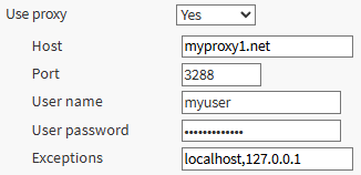
A proxy server acts as a gateway between the Barionet and other servers on the internet. "No": no proxy configuration required. "Yes": displays the parameters needed to connect through a proxy server — Host, Port, User name, User password, and Exceptions (a comma-separated list of addresses that bypass the proxy, e.g. localhost,127.0.0.1).
|
|
Avahi Announce |
When enabled, the Avahi service automatically broadcasts the Barionet's presence and services on the local network using multicast DNS (mDNS). It advertises a human-readable hostname ("barix-123456.local") that other devices on the same network can discover without knowing the specific IP address.
|
Time Settings
The Time Settings section allows you to configure Network Time Protocol (NTP) servers for automatic time synchronization on the device. NTP is a networking protocol designed to synchronize computer clocks across networks with high precision, by contacting designated time servers that maintain highly accurate time references.
None of the Barionet models offer a built-in Real Time Clock - the only way to set the device time is through NTP
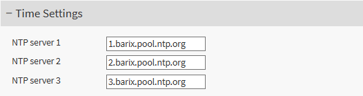
The device can be configured with up to three NTP servers for redundancy and reliability:
-
NTP server 1 (default 1.barix.pool.ntp.org)
-
NTP server 2 (default 2.barix.pool.ntp.org)
-
NTP server 3 (default 3.barix.pool.ntp.org)
The device attempts to contact these servers in order, starting with the first. Having multiple servers ensures the device can maintain accurate time even if one server becomes unavailable, which is crucial for logging, scheduling, and network operations that depend on precise timestamps.
Security Settings
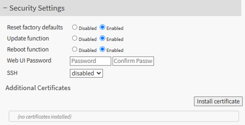
This section provides various security controls for device management.
|
Parameter |
Description |
|
Reset Factory Defaults |
Controls whether the device can be restored to its original factory configuration. When enabled, users can wipe all custom settings and return the device to its initial state via the DEFAULTS tab. It does NOT affect the hardware reset via button. |
|
Update Function |
Determines whether firmware updates can be installed on the device via the UPDATE tab. When enabled, the device can receive and install software updates. |
|
Reboot Function |
Controls whether the device can be remotely restarted through the REBOOT tab. When enabled, users can restart the device without physical access. |
|
Web UI Password |
Sets authentication credentials for accessing the web configuration interface. Users must enter and confirm a password that will be required to access the device's web-based management interface, preventing unauthorized configuration changes. Setting this password is the single most important step to secure a fielded device, because the same login also protects Flexa application uploads. |
|
SSH |
Controls Secure Shell access to the device. When enabled, it allows secure command-line access for advanced configuration and troubleshooting (intended for use by Barix personnel). Default: disabled. |
|
Additional Certificates |
Allows installation and overview of custom security certificates beyond the pre-loaded self-signed certificate. Use the "Install certificate" button to add trusted certificates. Organizations typically upload custom certificates to eliminate browser warnings, satisfy corporate security compliance, provide stronger identity verification, present a professional deployment, and integrate the device into an existing Public Key Infrastructure (chain of trust). These are outgoing, public-key-only certificates—for example, to allow other appliances in your infrastructure to trust the Barionet when it connects to them.
|
SNMP tab
SNMP (Simple Network Management Protocol) is a widely-used network protocol designed for monitoring and managing network devices across IP networks. It enables network administrators to remotely collect information about device performance, configuration, and status. SNMP operates on a client-server model where management stations query, or receive alerts from, SNMP-enabled devices, providing centralized visibility and control. The protocol uses a hierarchical database called the Management Information Base (MIB) to organize and standardize the information that can be monitored and managed across different devices and vendors.
The device provides a dedicated configuration tab for SNMP-related settings. The implementation supports SNMP versions 1, 2c and 3, a configurable port, the standard identification objects, community-based access (v1/v2c), user-based security with authentication and encryption (v3), and trap notifications—including traps triggered by changes on the digital inputs. The same Barionet I/O address map (see the "Developing Flexa Applications" part) is exposed as OID objects, so a management station can read and write I/O directly over SNMP.
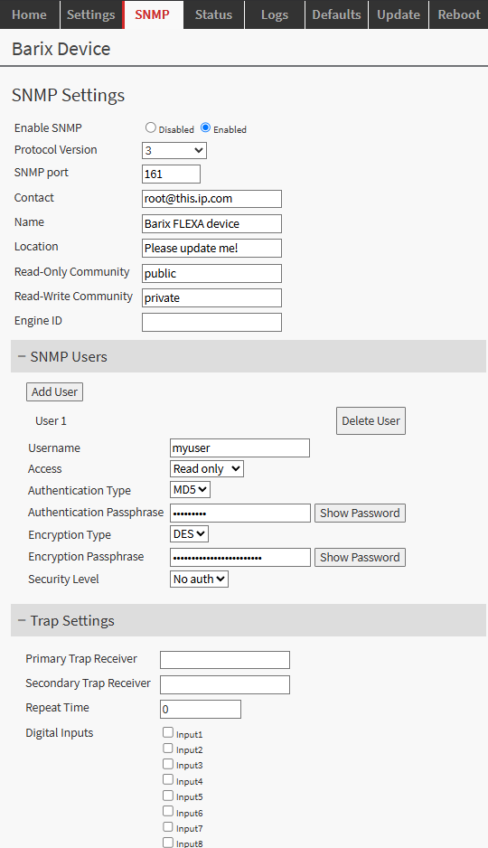
SNMP Settings
|
Parameter |
Description |
|
Enable SNMP |
Turns the SNMP agent on or off (Disabled / Enabled). When disabled, the device does not answer SNMP queries or send traps. Default: disabled |
|
Protocol Version |
Selects the version the agent uses: 1, 2c or 3. Versions 1 and 2c use the community strings below for access control. Version 3 replaces communities with user-based security (the "SNMP Users" section) providing authentication and optional encryption. Selecting version 3 reveals the SNMP Users options. Default: 1 |
|
SNMP port |
UDP port the agent listens on. Default: 161. |
|
Contact |
The device's sysContact object—a free-text administrative contact (for example an e-mail address) returned to management stations. |
|
Name |
The device's sysName object—a human-readable name identifying this unit. |
|
Location |
The device's sysLocation object—a free-text description of where the unit is installed. |
|
Read-Only Community |
Community string granting read access to the device's OIDs (v1/v2c only). Default: public. |
|
Read-Write Community |
Community string granting read and write access, allowing a manager to change writable I/O values, e.g. to set a relay (v1/v2c only). Default: private — change it and keep it confidential. |
|
Engine ID |
The SNMP engine identifier for this agent, used by SNMPv3 to uniquely identify the device within the administrative domain. Leave it blank to have one generated automatically; only letters and digits (no spaces or special characters) are accepted. |
SNMP Users (SNMPv3)
When Protocol Version is set to 3, access is no longer controlled by the community strings but by named users defined here, following the SNMPv3 User-based Security Model (USM). Use Add User to create an entry and Delete User to remove one; each user has the following settings:
|
Parameter |
Description |
|
Username |
The SNMPv3 user (security name) that a management station presents to authenticate. |
|
Access |
The rights granted to this user: Read only or Read write (read-write allows changing writable I/O values). |
|
Authentication Type |
The hashing algorithm used to verify the user's identity and message integrity: MD5 or SHA. Applies when the Security Level includes authentication. |
|
Authentication Passphrase |
The secret used with the Authentication Type to authenticate the user. Use "Show Password" to reveal what you typed. Choose a strong passphrase. |
|
Encryption Type |
The cipher used to encrypt (make private) the SNMP payload: DES or AES. Applies when the Security Level includes privacy. |
|
Encryption Passphrase |
The secret used with the Encryption Type to encrypt traffic for this user. Use "Show Password" to reveal it. |
|
Security Level |
How strongly this user's requests are protected:
|
Versions 1 and 2c do not use these user entries; they rely on the community strings above. Because v1/v2c communities are sent in clear text, prefer SNMPv3 with auth + priv whenever the network is not fully trusted.
Trap Settings
Traps are unsolicited notifications the device sends to a management station when an event occurs, rather than waiting to be polled. On the Barionet the traps are driven by the digital inputs: you choose which inputs are monitored, and the device sends a trap whenever one of them changes state. These settings apply to all SNMP versions, differing only in how the trap is authenticated (community for v1/v2c, user for v3).
|
Parameter |
Description |
|
Community |
The community string carried in the outgoing traps. Applies to SNMP v1 and v2c only (for v3 the "User" setting below is used instead, and this field is hidden). An empty value is accepted. |
|
User |
The SNMPv3 user whose credentials are used to send the traps. Shown only when Protocol Version is 3; it replaces the trap Community. Select one of the users defined in the SNMP Users section. |
|
Primary Trap Receiver |
The primary destination for traps, entered as IP_ADDR:PORT (for example 192.168.1.10:162).
|
|
Secondary Trap Receiver |
An optional second destination, in the same IP_ADDR:PORT form, that receives the traps as well (for redundancy).
|
|
Repeat Time |
While a monitored input remains active, the trap for it is re-issued repeatedly at this interval, in seconds. 0 disables repetition, so the trap is sent only on the state change itself.
|
|
Digital Inputs |
Selects which digital inputs are monitored for traps. Tick Input 1 … Input n (up to 4 on the Barionet M44, up to 8 on the M82); the device then sends a trap to the trap receivers whenever one of those inputs changes state—useful for alarm and access-control signalling without any custom application.
|
|
Enable trap at boot |
Controls whether a trap is sent for each trap-enabled input when the device boots. When Enabled (the default), immediately after start-up the device sends a trap reporting the current state of every monitored input, so the receiver learns each input's initial state without waiting for the first change. Set it to Disabled when a trap at boot would raise an undesired alarm (for example after a power cycle), so that traps are sent only on subsequent state changes. Default: Disabled |
I/O over SNMP. The same I/O address map used by Flexa applications is exposed through the device's MIB, so a management station can read inputs, analog values, counters and temperatures, and write relays and digital outputs, directly over SNMP, without any custom application. A read-write community (v1/v2c) or a v3 user with read-write access is required for write operations. This makes the Barionet usable as a plain SNMP-managed I/O device out of the box, in parallel with, or instead of, a Flexa application.
See also the IO Addresses map.
Status tab
The Status tab is a read-only page that reports the device's identity, network state, system information and licensing. It changes nothing on the device and is the quickest way to confirm which unit you are connected to, how it is addressed on the network, and that its firmware licence is valid. The information is grouped into the following sections.
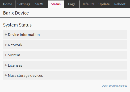
Device information
|
Field |
Description |
|
Hardware type |
The Barionet model and its hardware identifier, e.g. Barionet_M44 or Barionet_M82. Use this to confirm which product you are working with. |
|
IPAM type |
The internal IPAM compute module type and ID the firmware runs on. |
|
MAC address |
The Ethernet hardware address of the device useful for identifying the unit on the network and in DHCP reservations. |
|
Linux kernel version |
The full kernel version string, including the build toolchain and build date, of the running Flexa firmware. |
|
Bootloader version |
The version of the device's bootloader. |
Network
Shows the current state of the wired connection:
|
Field |
Description |
|
Status |
Whether the wired Ethernet link is Connected or not. |
|
IP address |
The IPv4 address currently in use by the device. |
|
Netmask |
The subnet mask in effect. |
|
Default gateway |
The gateway the device routes non-local traffic through. |
|
DNS servers |
The DNS servers in use, or Auto when they are obtained automatically (e.g. via DHCP). |
System
|
Field |
Description |
|
System time (refresh) |
The device's current date and time; the refresh link re-reads it. If this is wrong, correct it on the Settings → Time page. |
|
Uptime |
How long the device has been running since its last reboot. |
Licenses
Reports the status of the firmware licence that enables the Flexa platform on this unit. A valid, active licence is required for normal operation.
|
Field |
Description |
|
Name |
The licensed image/product, e.g. core-image-barix-flexa. |
|
Status |
Whether the licence is active. |
|
Issue date |
When the licence was issued. |
|
Expire date |
When the licence expires. |
|
ID |
The licence identifier. |
|
Features |
Any additional licensed features, or N/A if none. |
|
Signature |
Whether the licence's cryptographic signature is Valid. An invalid signature indicates a licensing problem—contact Barix support. |
Mass storage devices
Lists any USB mass-storage devices currently detected by the unit, or reports that none are present. Use this to confirm that a USB stick or drive intended for use by an application has been recognised. (Note that the USB port must be enabled for USB peripherals to be detected—see the USB notes in the "Developing Flexa Applications" part.)
Because the page only reports state, it is safe to leave open; refresh the browser to see updated values. To view live I/O values (inputs, relays, sensors) use a Flexa application or the SNMP interface; to change configuration use the relevant Settings tab.
Open Source Licenses
This link opens a tab where to consult all the open source modules, libraries, packages installed and used on the product and verify their license model.
Logs tab
The Logs tab shows the device's system log—the contents of the standard syslog (/var/log/messages)—directly in the browser. It is the primary way to see what the device and any installed Flexa application are doing, without needing shell access to the unit.
The log is where a Flexa application's diagnostic output appears: anything the application writes with the standard logging facility is interleaved with the firmware's own messages, each line time-stamped and tagged with the process that produced it. This makes the Logs tab the first place to look when commissioning or troubleshooting an application—for example to confirm that the app started, that it connected to the io-mapping service, or to read a warning it emitted (such as a failure to detect a USB-connected UX8 extension).
Typical uses:
-
Confirm that a newly installed application launched and is running.
-
Read application status and error messages emitted during operation.
-
Diagnose network, USB or peripheral problems reported by the firmware.
-
Capture a snapshot of recent activity to attach to a support request.
The view can be refreshed to show the latest entries. Because the log has a bounded size, older lines are eventually rotated out; copy anything you need to keep. For guidance on writing well-behaved log output from your own application, see the "Logging" section in the "Developing Flexa Applications" part of this manual.
DEFAULTS tab
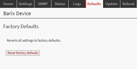
The DEFAULTS tab restores the device to its factory configuration. Using it clears security settings (default password is restored), Time Settings, SNMP settings, and any installed Flexa application configuration and returns the unit to the state it shipped in. Use it when repurposing a device, recovering from a misconfiguration, or before handing a unit to another user.
The reset applied via web config does NOT restore network settings to defaults. Only the physical hardware reset button does.
This function is available only when Reset Factory Defaults is enabled on the Settings → Security page; if that control is disabled, the DEFAULTS tab will not perform a reset.
After confirming the reset the device reboots.
UPDATE tab
The UPDATE tab installs firmware onto the device. It shows the currently installed firmware version and lets you upload a Flexa firmware image supplied by Barix; the device then verifies and applies it and reboots into the new version.
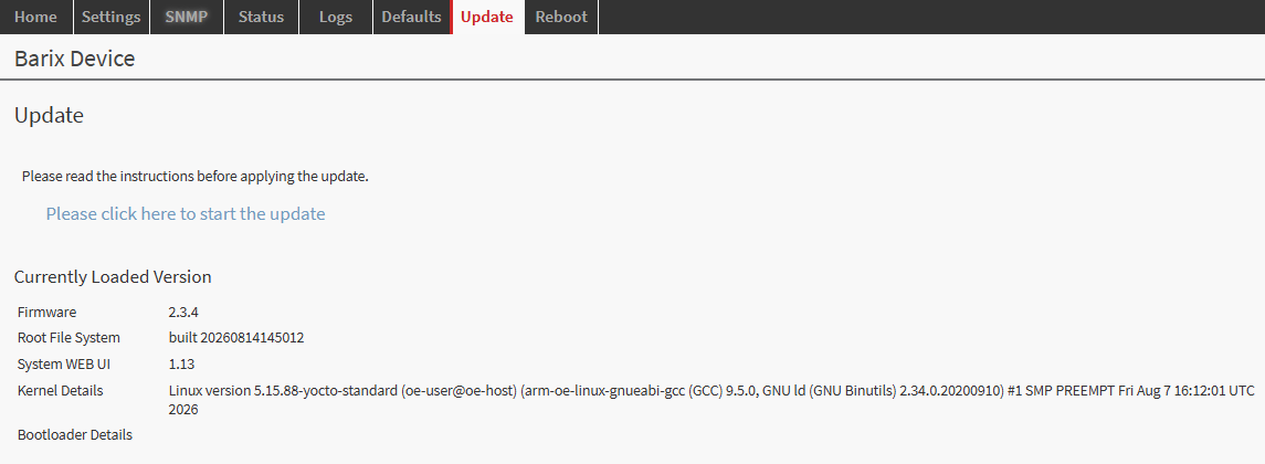
This function is available only when the Update Function is enabled on the Settings → Security page. Keep the firmware current so the device carries the latest features and security fixes. Do not remove power during an update, and use only firmware images provided by Barix.
How to update the firmware:
-
Download the firmware from https://help.barix.com/barionet/downloads
-
Follow the on-screen instructions and upload the .tar file of the image onto the device (do not un-compress the image on your PC)
-
Once the update starts a progress bar indicates the status of the update
-
When the update completes, the device reboots into the new version
REBOOT tab
The REBOOT tab restarts the device remotely, without requiring physical access or a power cycle. A reboot is a common way to force a fresh start of the Flexa application, to re-run network discovery (for example after changing DHCP/static settings), or to re-synchronize with the Flexa service portal.
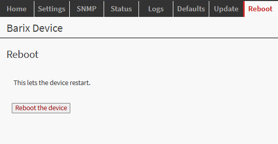
This function is available only when the Reboot Function is enabled on the Settings → Security page. Rebooting interrupts any running application and drops network connections for a few seconds while the device restarts; relays and outputs return to their power-on state during the restart, so consider the effect on connected equipment before rebooting a live installation.
Developing Flexa Applications
This part is the developer reference for the Barionet M44 and M82. It consolidates the material previously spread across the online Barionet for-developers pages: the I/O address map, the io-mapping API, the configuration options (SDF or a custom web interface), the supported programming languages, the serial and Wiegand (BM82 only) interfaces, and UX8 expansion. If you prefer to be guided rather than read the whole reference, Barix provides a Claude AI skill that generates a complete, deployable application from a plain-language description — see "Accelerating development with the Claude AI skill" at the end of this part.
What a Flexa application is
A Flexa application is a small package (a ZIP) that the device unpacks and runs as a normal Linux program. The firmware manages its lifecycle through a watchdog, so the developer only writes the application logic. The runtime contract is:
-
The package is unpacked to /mnt/data/package, which becomes the application's working directory.
-
The application is started under a watchdog that restarts it whenever it exits; design the app as a long-running loop rather than a one-shot program.
-
On stop or restart the firmware sends SIGTERM (then SIGKILL after ~10 seconds); handle SIGTERM to shut down cleanly.
-
The application is restarted every time the configuration form is saved; start cleanly from the stored configuration each time and do not rely on in-memory state surviving a save.
-
The application runs with full (root) privileges. Treat an installed package as trusted software (see "Security and hardening").
-
Log output sent to the system log appears in the device's LOGS tab, which is the main way to observe an application at runtime.
Getting an application onto a device
There are two supported ways to deploy an application:
-
Local install — from the HOME tab, "Install Package" uploads a ZIP directly to the device.
-
Flexa service portal — the device retrieves its application (and updates) from the Barix Flexa cloud registry, identified by its RegID. This is used for managed, fleet-wide distribution.
Package structure
A Flexa application is delivered as a ZIP archive. Inside it are an install descriptor, the application code, and — optionally — a configuration form and any system files the app needs. The archive may hold these at its root, or inside a single package/ wrapper folder; the installer accepts both. On installation the package is unpacked to /mnt/data/package on the device, and that directory is the application's working directory at run time.
|
Item |
Purpose |
|---|---|
|
|
Install descriptor (required, at the package root): the entry point that starts the app, firmware requirements, the configuration form (SDF), and any extra system files to install. Details below. |
|
|
The application code. Python and Lua are interpreted on the device; C/C++/Rust are cross-compiled to a binary that you ship inside the package. |
|
|
The Settings Definition File that declares the configuration form shown in the web UI (optional; see "Configuring an application"). |
|
|
The stored settings, written by the firmware when the form is saved. The app reads it at start-up. Not present on a first install (see "Configuration lifecycle"). |
|
|
Optional. A small file |
|
|
Optional. A folder of web files for a custom web interface; when present it is served by the device at |
install.json
install.json is read by the on-device installer. Its most important job is to declare the entry point — the command that launches your app — but it also controls firmware compatibility, the settings form, and extra files to drop into the filesystem. It must be valid JSON (no trailing commas).
Example (a Python app with a settings form and three system files):
{
  "entryPoint": "/usr/bin/python3 run.py",
  "minFwVersion": "2.3.4",
  "name": "BACNET_IO_SERVER",
  "sdf": {
    "file": "config/sdf.json",
    "tabName": "BACnet"
  },
  "files": [
    { "name": "alsa/app-sound.conf", "dest": "/etc/barix" },
    { "name": "uci/application", "config": true },
    { "name": "cm6533/cm6533", "dest": "/etc/init.d", "updaterc": "defaults 99" }
  ]
}
Top-level fields
|
Field |
Required |
Meaning |
|---|---|---|
|
|
Yes* |
The command that starts the app, run from the package directory — e.g. |
|
|
No |
The application name used by the system and shown in the UI. May also come from |
|
|
No |
Minimum firmware version the app needs, as |
|
|
No |
URL of the firmware image to fetch for |
|
|
No |
The settings form: |
|
|
No |
A list of extra files to install into the device filesystem (see below). |
If entryPoint is omitted, the installer accepts the legacy field run with the same meaning; if neither is present it falls back to a file named run.py, then default.lua, in the package root.
The files list — installing files into the system
Each entry copies one file from the package into the device filesystem. This is useful for ALSA plugins, system (UCI) configuration defaults, init scripts, and similar supporting files.
|
Key |
Required |
Meaning |
|---|---|---|
|
|
Yes |
Path of the file inside the package. It keeps its base name when installed. |
|
|
Yes (unless |
Destination directory on the device (created if it does not exist). |
|
|
No |
If present, the file is installed as a system (UCI) configuration default into |
|
|
No |
File permissions to apply, as a decimal integer (for example |
|
|
No |
Register the file (placed in |
In the example above: app-sound.conf is copied to /etc/barix/; application is installed as a UCI configuration default; and cm6533 is placed in /etc/init.d and registered to start at boot with defaults 99.
How the application is launched
-
The app runs with its working directory set to
/mnt/data/package, so relative paths and bundled files resolve against the package root. -
The app is launched and supervised by the
barix-wdwatchdog: if it exits or crashes it is automatically restarted (the respawn is throttled to about 10 seconds when the app dies immediately after starting), and on stop it is force-killed if it does not exit within about 10 seconds. -
Because the entry point is executed as a command, prefer the explicit-interpreter form (
/usr/bin/python3 main.py); it does not depend on the entry file's execute bit. -
For a Lua entry point, the package directory is added to the Lua module search path automatically (
LUA_PATHincludes<package>/?.lua), so your own.luamodules shipped in the package are found; system C modules are available viaLUA_CPATH.
Configuration lifecycle
On the very first install, before the configuration form has ever been saved, config.json does not exist yet — the firmware does not create it. A well-behaved application therefore ships with, or writes on first start, a set of built-in defaults, so it runs correctly out of the box. When the user saves the form, the firmware writes config.json (at /mnt/data/package/config.json) and restarts the app. The app should always read its settings on top of its in-code defaults, so that a missing or new key never breaks it.
Custom web interface
If the package contains a web_ui/ folder, the installer publishes it at <http://<device>>/app. This lets an app ship a bespoke status/control page in addition to (or instead of) the SDF settings form. See "SDF or a separate web configuration" for when to choose each.
The I/O model: the io-mapping service
All physical I/O on the Barionet M44 and M82 is owned by a single system service, io-mapping. Applications never touch GPIO or hardware registers directly; instead they read and write numbered I/O addresses through the service. The same address map is used by the Python and Lua bindings, by SNMP, by Modbus, and (for native code) by a D-Bus interface or the kernel sysfs files. Using one consistent address space means the same application logic works on both devices and automatically spans attached UX8 extensions.
I/O address map
The address layout is identical on both models; only the counts differ. The units and conventions for each type are given inline in the table below. Every address is a signed integer; writing to a read-only (R) address is rejected with an error.
|
Address |
R/W |
Barionet M44 |
Barionet M82 |
|
1–4 |
R/W |
Relays 1–4 (0 = open, 1 = closed) |
Relays 1–2 (0 = open, 1 = closed; 3–4 unused) |
|
9 |
R/W |
Serial RTS output (0/1) |
Serial RTS output (0/1) |
|
101–104 |
R/W |
— |
Digital (solid-state) outputs 1–4 (0/1) |
|
201–208 |
R |
Digital inputs 1–4 (1 = contact closed to ground) |
Digital inputs 1–8 (1 = contact closed to ground) |
|
209 |
R |
Serial CTS input (0/1) |
Serial CTS input (0/1) |
|
301–308 |
R/W |
Input pull-ups 1–4 (1 = on; on by default) |
Input pull-ups 1–8 (1 = on; on by default) |
|
401–408 |
R/W |
Input counters 1–4 (count input transitions; write 0 to reset) |
Input counters 1–8 (count input transitions; write 0 to reset) |
|
501–508 |
R |
Analog inputs 1–4 (millivolts, 0–15 V range) |
Analog inputs 1–8 (millivolts, 0–15 V range) |
|
601–650 |
R |
1-Wire temperatures (milli-°C, i.e. ÷1000 for °C; 4096 = no sensor) |
1-Wire temperatures (milli-°C, i.e. ÷1000 for °C; 4096 = no sensor) |
|
651–750 |
R |
1-Wire sensor IDs (one per temperature slot) |
1-Wire sensor IDs (one per temperature slot) |
|
1201 / 1202 |
R |
Supply current (mA) / supply voltage (mV) |
Supply current (mA) / supply voltage (mV) |
|
1203 / 1204 |
R |
CPU temperature (milli-°C) / uptime (seconds) |
CPU temperature (milli-°C) / uptime (seconds) |
|
1205 / 1206 |
R |
Hardware type (82) / firmware version |
Hardware type (98) / firmware version |
|
1207 |
R/W |
USB ports enable (1 = enabled; peripherals need this on) |
USB ports enable (1 = enabled; peripherals need this on) |
|
1208–1211 |
R/W |
User LED colour (1–7; 0 rejected) / brightness (0–15) |
— (reserved) |
|
11–42 |
R/W |
UX8 relays (units 1–4, 8 each; 0/1) |
UX8 relays (units 1–4, 8 each; 0/1) |
|
211–242 |
R |
UX8 digital inputs (0/1) |
UX8 digital inputs (0/1) |
|
411–442 |
R/W |
UX8 input counters (write 0 to reset) |
UX8 input counters (write 0 to reset) |
|
511–542 |
R |
UX8 analog inputs (millivolts) |
UX8 analog inputs (millivolts) |
|
1212–1243 |
R/W |
UX8 analog-input enable bits (1 = enabled) |
UX8 analog-input enable bits (1 = enabled) |
|
43–100, 109–200, 210, 243–300, 309–400 |
R/W |
Virtual I/O bits (1-bit scratch registers; see note) |
Virtual I/O bits (1-bit scratch registers; see note) |
|
409–410, 443–500, 509–510, 543–600 |
R/W |
Virtual I/O registers (16/32-bit scratch; see note) |
Virtual I/O registers (16/32-bit scratch; see note) |
|
60001–60006 |
R |
Interface counts (serials, relays, outputs, inputs, analog) |
Interface counts (serials, relays, outputs, inputs, analog) |
|
60007–60010 |
R |
UX8 units 1–4 detected (1 = present) |
UX8 units 1–4 detected (1 = present) |
Virtual I/O. The address space contains ranges that are not backed by physical hardware; these behave as read/write scratch registers (the 1-bit ranges hold 0/1, the wider ranges hold 16- or 32-bit values). They are free general-purpose storage that any subsystem can read and write, so they are handy for passing values between an application and the other interfaces that share the same address map — SNMP, Modbus and the web UI — or as simple shared state between processes. On a device without UX8 extensions, the extension ranges (addresses 11–42, 211–242, and so on) are likewise available as virtual I/O until a UX8 is attached.
Change notifications are available for the 1-bit I/O types — relays, digital outputs, digital inputs and pull-ups — so an app can react to an input closing instead of polling. Analog inputs, counters, temperatures and the system registers must be polled.
Hardware timed pulse
A relay or digital output can be switched on and then released automatically after a set time, with the timing performed by the on-board co-processor rather than by the application. Because the co-processor keeps the count, the output still releases at the right moment even if the application is restarted or stops mid-pulse — which makes this the correct way to drive door strikes, gates, and watchdog-style outputs where a stuck-on output would be a problem.
The pulse is triggered through the kernel's sysfs interface (the io-mapping write_value call only sets a steady 0 or 1, so it is not used for timed pulses). Each relay and digital output exposes a timed_set file under the device's sysfs tree:
-
Base path:
/sys/kernel/bm44on the Barionet M44,/sys/kernel/bm82on the M82. -
Relays:
relays/<n>/timed_set; solid-state digital outputs (M82):outputs/<n>/timed_set. -
Writing a number N drives the output active immediately and releases it automatically after N × 100 ms (so 20 = 2 seconds).
-
Reading returns the time remaining, in the same 100 ms units, or -1 when no pulse is active.
Python — pulse relay 1 for two seconds:
BASE = "/sys/kernel/bm44"            # "/sys/kernel/bm82" on the M82

# 20 x 100 ms = 2 s; the relay closes now and re-opens by itself after 2 s
with open(BASE + "/relays/1/timed_set", "w") as f:
    f.write("20")

# optional: how much pulse time is left (100 ms units, -1 when finished)
remaining = int(open(BASE + "/relays/1/timed_set").read())
print("remaining 100 ms units:", remaining)
Lua (5.1):
local BASE = "/sys/kernel/bm44"      -- "/sys/kernel/bm82" on the M82

-- 20 x 100 ms = 2 s pulse on relay 1
local f = io.open(BASE .. "/relays/1/timed_set", "w")
f:write("20")
f:close()

-- optional: read the remaining time (100 ms units, -1 when finished)
local r = io.open(BASE .. "/relays/1/timed_set", "r")
print("remaining 100 ms units:", r:read("*n"))
r:close()
For a solid-state output on the M82, use outputs/1/timed_set (and so on) instead of relays/1/timed_set. The same files are reachable from a native C/C++ or Rust application as ordinary file writes, with no library dependency.
Accessing I/O from Python and Lua
The pre-installed io-mapping module exposes the service with an identical API in both languages: read one or many addresses, write an address, discover which addresses exist on this device, and subscribe to change notifications.
Python:
from iomapping import IoMapping, RegisterType
io = IoMapping()
io.write_value(1, 1)                    # relay 1 on
level = io.read_value(501)              # analog input 1, in mV
inputs = io.read_values([201, 202, 203, 204])
relays = io.get_addresses(RegisterType.RELAY)   # [1,2,...] incl. UX8 if present
io.enable_notifications(201, lambda addr, val: print(addr, val))
while True:
    io.run(False)                       # dispatch notification callbacks
Lua (the interpreter is Lua 5.1; register types are passed as integers):
require("iomapping")                     -- provides the global IoMapping
local s = IoMapping.new()
s:write_value(1, 1)                      -- relay 1 on
local level = s:read_value(501)          -- analog input 1, in mV
local relays = s:get_addresses(0)        -- 0 = RELAY (see the integer table)
s:enable_notifications(201, function(addr, val) print(addr, val) end)
while true do s:run(false); require("socket").sleep(0.05) end
Lua register-type integers for get_addresses:
0 = relay
1 = digital output
2 = digital input
3 = pull-up
4 = counter
5 = analog input
8 = temperature value
11/12 = supply current/voltage
13 = CPU temperature
14 = uptime
15 = USB enable
18 = hardware type
19 = firmware version
26 = UX8 detected
27 = analog enable.
get_addresses() returns only the addresses that physically exist on this device, in connector order and including any attached UX8 I/O, which is the reliable way to write code that runs on both the M44 and M82.
Accessing I/O from C/C++ and Rust
A compiled application reaches the same I/O in one of two ways:
-
sysfs — the kernel driver exposes each I/O as a plain file under
/sys/kernel/bm44(M44) or/sys/kernel/bm82(M82), e.g.relays/1/value,inputs/3/value,outputs/1/timed_set. This needs no libraries, but analog values here are raw ADC counts (not millivolts) and there are no change notifications. -
D-Bus — the io-mapping service is on the system bus as
org.barix.IoMapping, object/org/barix/register, interfaceorg.barix.Registerwith methodsRead(address),Write(address, value),ReadList,GetAddrsPerType,GetParams, and a broadcast signal OnValueChange(address, value). This gives the same scaled values and notifications the Python/Lua bindings use.
Use sysfs for a simple, dependency-free app; use D-Bus when you need calibrated analog values or push notifications from native code.
Configuring an application: SDF form or custom web interface
Every application can present a configuration tab in the device web UI. There are two ways to build it; they can also be combined (a settings form plus a live page).
SDF (Settings Definition File)
SDF is a JSON description of a settings form. The application ships config/sdf.json; the firmware reads it and renders the form automatically — labels, defaults, dropdowns, sliders, toggles, password fields, repeating lists and conditional fields — without any front-end code. When the user presses Save, the firmware validates the values, writes them to config.json (nested by section), and restarts the application, which reads the new values on startup. SDF is the right choice when the UI is configuration that takes effect on save. An interactive playground for designing an SDF form is available online; the field types and structure are documented in the developer reference and generated for you by the Claude AI skill.
Barix provides an online playground where you can paste or write an SDF and instantly see the rendered form:
http://sdf-playground.s3-website.eu-north-1.amazonaws.com/
Use it to prototype and iterate quickly before shipping your SDF.
More details on how to develop your SDF are available at this link:
https://help.barix.com/barionet/ui-programming-settings-definition-file-sdf-overvi
Custom web interface
When you need a live status page, action buttons, charts or a bespoke layout, an application can ship a set of web files that the device serves at http://<device>/app/, and (for live data) run its own small HTTP server on a separate port. This is the right choice when the page must show real-time values or act immediately rather than only on save. A custom page served this way sits behind the same device login as the rest of the web UI; a separate app HTTP server is not authenticated unless the app adds it, so keep it on a trusted network or make sure your app considers authentication.
Programming languages
The Barionet runs applications in different languages. Choose based on effort, footprint and whether you need native performance. Below is a table with notes on the 4 tested and knowing to work languages used to develop apps for Barionets so far.
|
Language |
Notes |
|
Python 3 (default) |
The whole pre-installed library set (requests, paho-mqtt, pymodbus, flask, cryptography, pyserial, and more), the shortest path to a working app. Recommended unless there is a specific reason to choose otherwise. |
|
Lua 5.1 |
Small footprint or existing Lua code. The io-mapping API is identical to Python's; socket, cjson, mosquitto (MQTT) and serial libraries are available. |
|
C / C++ |
For hard real-time loops, heavy computation or reuse of native code. There is no compiler on the device; cross-compile on a host for armv7 hard-float, glibc 2.31 (or link statically). |
|
Rust |
The same use cases as C/C++ with memory safety; cross-compile for the armv7 target, preferably a fully static musl binary so it has no library dependencies on the device. |
There is no package manager for end users on the device: Python and Lua apps may only use the libraries already installed in the firmware (no pip install). The developer reference lists exactly what is available.
Serial interfaces (RS-232 / RS-485)
The RS-232 port is /dev/ttyS1 on both models (its RTS/CTS lines are also visible as I/O addresses 9 and 209). The Barionet M82 has a second serial port, /dev/ttyS2, with a transmit-enable line for half-duplex RS-485-style buses. (The port /dev/ttyS0 is the Linux debug console and must never be used by an application.) Python provides pyserial and pymodbus; typical uses are a serial-to-network gateway, polling a Modbus device, or parsing a line-based protocol. Baud rate, parity and framing are normally exposed to the user through the configuration form.
Wiegand card readers (Barionet M82)
The M82 has two independent Wiegand reader interfaces, decoded in hardware and presented as character devices /dev/wiegand0 and /dev/wiegand1. Their data lines share input terminals 5–8 (reader 1 uses terminals 5 and 6, reader 2 uses terminals 7 and 8); there is no mode to switch — the readers decode continuously, in parallel with the normal input function of those terminals. Each card read is delivered as one frame: a leading byte giving the number of bits, followed by the card bits. The common 26-bit (H10301) and 34-bit formats decode into a facility code and card number; other formats are readable as raw values. Because the terminals double as digital inputs, an application should ignore inputs 5–8 as ordinary contacts when readers are wired, and filter incoming frames by their expected bit length.
UX8 I/O expansion
Up to four Barionet UX8 units attach over USB, each adding 8 relays, 8 digital inputs, 8 counters and 8 analog inputs (no pull-ups or digital outputs). Their addresses continue the base map (relays 11–42, inputs 211–242, counters 411–442, analog 511–542), and get_addresses() includes them automatically, so an application written with the helper spans base and extension I/O with no special code.
Three UX8 specifics matter for robust applications:
-
Detection is a start-up snapshot. Addresses 60007–60010 report which units were present when the io-mapping service started; they do not update if a unit is unplugged later. Do not use them as a live health check.
-
UX8 analog inputs must be enabled (their enable bit, 1212+) before they read anything.
-
A UX8 is USB, so it can drop out at runtime. A unit that was present at start but stops responding causes reads and writes to its addresses to fail (rather than return stale data); an application should detect this, warn (its log line appears in the LOGS tab if written in
/var/log/messages), and continue operating the on-board I/O. Note also that on a device with no UX8 present at boot, the firmware powers the USB ports off (I/O address 1207); an application that uses any USB peripheral must ensure USB is enabled.
Accelerating development with the Claude AI skill
Barix publishes a Claude AI "skill" that turns a plain-language description into a complete, deployable Barionet application. It asks a short set of questions (which device, what the app should do, which I/O and settings, which language), proposes a plan, then generates the manifest, the application code, the SDF configuration form (or a custom web UI) and a validated, ready-to-upload ZIP — using the exact I/O addresses, io-mapping API and packaging described in this part. It supports the Barionet M44 and M82, all four languages, serial, Wiegand and UX8.
See the full guide, including how to install the skill into your Claude account and an annotated example session: Your Own Flexa Application for Barionet with Claude AI. The skill is a development aid; the resulting application is deployed and secured exactly like a hand-written one.
Logging and debugging
An application should log through the system log (syslog). Those lines are collected into /var/log/messages and shown in the device's LOGS tab console, which is the primary way to observe an application — end users do not have shell access. The LOGS tab also offers a download of the full log archive plus diagnostics. For centralised monitoring, an application can additionally forward its log to a remote syslog server, typically made configurable through its settings form.
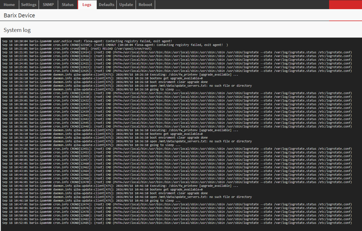
Security and hardening
A Flexa application runs with full privileges, so the security of a fielded Barionet rests on controlling who can install a package and on how the device is exposed:
-
Set the Web UI Password (Settings → Security). The same login protects application uploads; a device left without a password lets anyone on the network install and run code.
-
Keep the device, and any port an application opens, on a trusted network behind a firewall; do not expose the Barionet directly to the public internet.
-
Install only applications you trust, and keep the firmware up to date via the UPDATE tab.
-
In the applications you build: do not hard-code secrets (expose them through the configuration form), validate data arriving from serial/network/Wiegand, and remember that an app's own web server is unauthenticated unless you add authentication.
-
Use HTTPS to interact with the Barionet web GUI so to encrypt the communication with browsers accessing the unit.
-
Change the default password and store your own strong password in a safe place.
Application responsibility and security boundary
A Flexa application is not a sandboxed plug-in. When installed, the package is unpacked to /mnt/data/package and its entry point runs as root, supervised by the device watchdog. That application can read and write every device I/O, open its own TCP/UDP network services, install files into the system (init scripts, configuration defaults, permissions), pull in bundled dependencies, and otherwise change how the device behaves. This power is by design — it is what makes the Barionet programmable — and it means that an application, not the base firmware, determines most of the device's runtime behaviour and a large part of its attack surface.
Trust boundary. Barix provides and maintains the hardware, the firmware, and the Flexa platform, including the authenticated device web interface used to install and manage applications: installing or updating an application, uploading configuration, updating firmware, and rebooting all require administrator authentication. What runs inside an installed application, and any interface that application chooses to expose, is outside that boundary and under the control of whoever wrote and deployed the application.
In particular, a network service that an application opens is not automatically protected by the device login. For example, an app that starts its own HTTP or MQTT server, or that relies on the settings-form backend, is reachable on the port it binds; unless the application (or its configuration) enforces its own authentication and, where appropriate, encryption, that service is exposed on the network without the device's credentials. Choosing which ports to open, how to authenticate them, what to log, and what privileges to exercise is the application's responsibility.
Disclaimer. Barix is not responsible for any Flexa application installed on a device — whether developed by the customer, by a third party, or generated with the assistance of a tool such as the Claude AI skill — nor for any consequences of installing or running it. This includes, without limitation: damage to connected equipment or processes; loss, corruption, or disclosure of data; unsafe or unintended physical actuation (relays, outputs, connected machinery); and any security weakness the application introduces or fails to prevent, such as open or unauthenticated network services, weak or absent credentials, exposed configuration or control interfaces, insecure handling of secrets, or vulnerabilities in the application's own code or its dependencies. Responsibility for the design, review, testing, security, safe operation, and maintenance of an application, and for the decision to deploy it on a given network, rests with the party that develops and/or installs it.
Operator and developer responsibilities. To keep a deployment secure, the party deploying an application should, at minimum: review the application's source and understand what it does before installing it; keep the device firmware current; set a strong administrator password (and a strong root password, or disable SSH, where shell access is enabled); restrict the device and any app-opened ports to trusted networks (for example behind a firewall or VPN); review every additional service, port, and system file the application adds; avoid default or shared credentials and community strings (e.g. SNMP); and re-assess these points whenever the application or its configuration changes.
Applications generated with AI assistance. A tool that helps generate a Flexa application — including the Barix Claude AI skill — is an aid to development, not a guarantee of correctness or security. Generated code must be reviewed, tested, and secured by the developer exactly as any hand-written application would be, and the responsibilities and disclaimer above apply to it in full.