|
Version |
Changelog |
Date |
Download |
|---|---|---|---|
|
2.0.0 |
Initial Release |
||
|
2.2.0 |
|
|
Application Version: 2.2.0
Compatible Firmware: Flexa Firmware min. v2.3.0
Device Compatibility: Barionet M44, UX8 Extension
Overview
The IO Tunnel Application creates a network bridge between digital inputs and outputs on Barionet devices, allowing you to control relays on one device by activating inputs on another device across your network. This powerful feature enables distributed control systems where physical separation between input sensors and controlled equipment is required.
The application works bidirectionally, meaning both devices can simultaneously send and receive IO state changes. When a digital input closes on Device A, it can immediately activate a relay on Device B, and vice versa. This creates a transparent "tunnel" for IO signals that operates in real-time over your existing Ethernet network.
Compatible Hardware
Primary Platform: The IO Tunnel Application is designed for Barionet M44 devices running the Flexa Firmware v2.3.0.
Extension Support: When a UX8 extension module is connected via USB, the system gains an additional 8 digital inputs and 8 relays, bringing the total capacity to 12 inputs and 12 relays per device.
Legacy Compatibility: The application maintains full backward compatibility with older Barionet models including the Barionet 50 and Barionet 100. This offers “mixed” installation possibilities.
Note for Barionet 100 Users: When working with Barionet 100 devices, the UX8 input mapping differs from M44 devices. On Barionet 100, what the IO Tunnel application refers to as "UX8 Input 1 through 4" actually corresponds to "Input 5 through 8" on the physical Barionet 100 device. This mapping ensures proper compatibility between different device generations.
Installation Process
Installing the IO Tunnel Application requires uploading a package file directly to your Barionet device through its web interface. This process is straightforward but requires careful attention to ensure proper installation.
NOTE: If your Barionet M44 is already running an application you must RESET TO DEFAULTS before proceeding and installing a new one.
Step 1: Access the Device Web Interface
-
Open your web browser and navigate to your Barionet device's IP address
-
Enter your administrator username and password when prompted
-
Wait for the main interface to load completely before proceeding
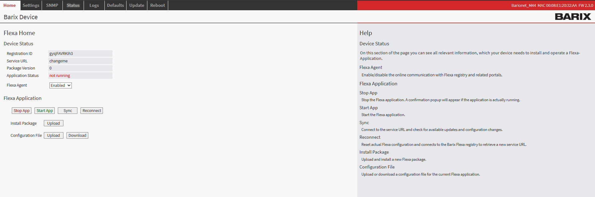
Barionet M44 User Interface
Step 2: Upload the Application Package
-
Navigate to the HOME tab in the main menu
-
Locate the "Upload" button next to “Install Package” within the page
-
Click the file selection button and browse to the “package.zip” which was downloaded from this page
-
Choose an appropriate version number for tracking purposes (this can be any number you prefer for identification)
-
Click the UPLOAD button to begin the installation process
Step 3: Device Reboot and Verification
After the upload completes, your Barionet device will automatically initiate a reboot sequence. This reboot is necessary to properly integrate the new application into the system. The reboot process typically takes 30..40s
-
Wait for the device to complete its reboot cycle
-
Reconnect to the web interface using the same IP address and credentials
-
Navigate back to the HOME tab
-
Verify that the IO Tunnel application appears with a status of "running"
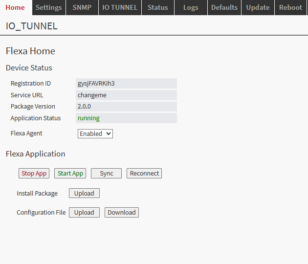
Barionet M44 Home Tab
Configuration Overview
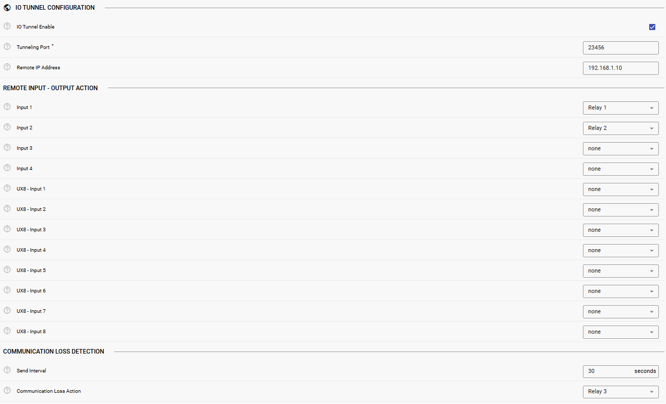
Once successfully installed, the IO Tunnel application configuration interface becomes available through the IO TUNNEL tab in your device's web interface. This dedicated configuration page provides access to all settings necessary to establish communication between devices and configure input-to-relay mappings.
The configuration system is designed to be intuitive while providing the flexibility needed for complex installations. Each setting includes helpful descriptions and validation to prevent configuration errors that could disrupt communication.
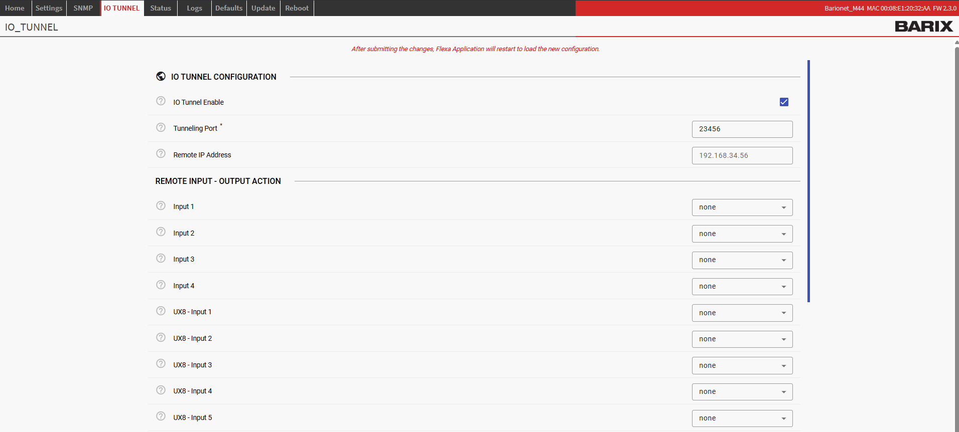
Main Configuration Settings
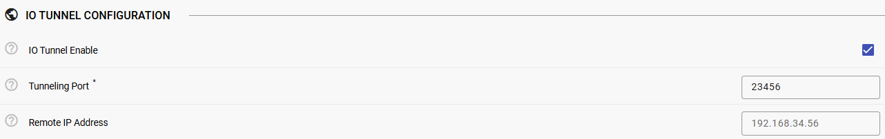
Enabling the IO Tunnel Service
The IO Tunnel Enable setting acts as the master control for the entire application. When enabled, the service begins monitoring local inputs and establishes network communication with remote devices. When disabled, all IO monitoring and network communication stops.
Network Communication Setup
Tunneling Port Configuration: The tunneling port defines which UDP port your device uses for both sending and receiving IO tunnel messages. This port must be the same on the devices participating in the IO tunnel network.
Remote Target Address: This setting specifies the target address where to send IO data, it is the address of the other Barionet participating in the IO Tunnel. You can configure this in two ways:
Leave this field empty if you want the device to only receive data without sending any outgoing message.
Input Trigger Mapping
The heart of the IO Tunnel system lies in its flexible input-to-relay mapping capability. This system allows you to define exactly which relay on the local device should activate when a specific input changes state on the remote device.
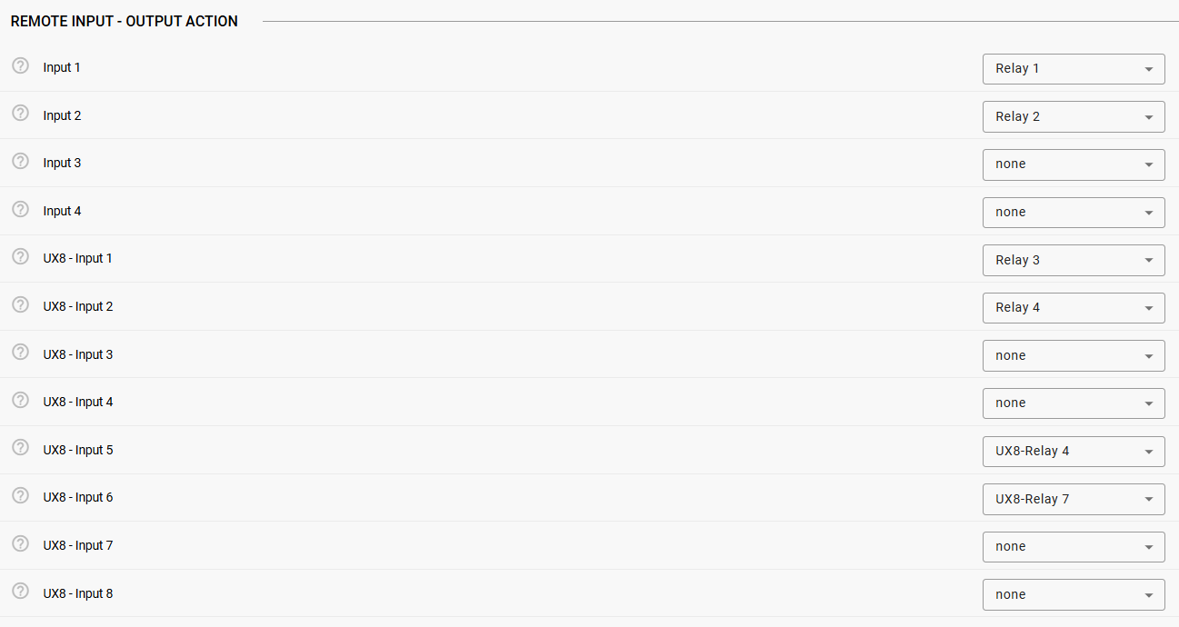
REMOTE INPUT - OUTPUT ACTION
Based on the remote input state we can map a local output action (relays) to be controlled.
-
Setting to none: No action occurs when the remote input changes.
-
Setting to Relay 1- Relay 4: Controls the corresponding built-in relay (1, 2, 3, or 4) when the corresponding remote input changes state.
UX8 Extension Input Configuration
When a UX8 extension module is connected, eight additional IOs become available for configuration. These UX8 IOs provide the same mapping flexibility as built-in IOs but with expanded control options:
-
Setting to UX8 Relay 1- UX8 Relay 8: Controls UX8 extension relays 1-8 when the corresponding remote input changes state.
This flexibility allows you to create complex control scenarios where multiple remote inputs can control the same local relay, or where remote UX8 inputs control built-in relays and vice versa.
Communication Loss Detection and Recovery
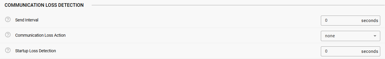
Send Interval Configuration: The send interval determines how frequently your device transmits its current IO status to the remote Barionet, regardless of whether any inputs have changed. This setting works in addition to the immediate notifications sent when inputs change state.
-
Setting to 0: Disables periodic transmission. Your device will only send messages when an input actually changes state.
-
Setting to any positive number: Enables periodic transmission every specified number of seconds. For example, setting this to 30 means your device will send a status update every 30 seconds, even if no inputs have changed.
Periodic transmission serves as a heartbeat mechanism, allowing the remote device to detect communication failures and ensure both devices maintain synchronized status information.
The IO Tunnel application includes sophisticated communication monitoring that automatically detects when network communication with the remote device fails and takes appropriate action.
Startup Loss Detection: This interval is configured to allow the app to detect loss detection right after startup in case no “status update” packet can be received by the remote Barionet.
Any positive value enables the startup loss detection, by setting this value to “0” disables it.
Any packet received after startup by the remote Barionet will overwrite the Startup Loss detection, in practice, disabling it.
Example 1: Remote Barionet doesn’t send any packet after application startup → The application waits for the startup loss detection interval (if > 0) and then logs the communication loss and triggers the communication loss action (if configured).
Example 2: Remote Barionet sends packets (either status or input triggers) while startup detection is waiting for its interval to expire → The application will overwrite the startup detection with the send interval provided by the remote Barionet in the packet received (see Protocol details in following chapters).
How Communication Monitoring Works
The system uses a intelligent timeout mechanism based on the remote device's configured send interval. When your device receives a message from the remote device, it examines the send interval value contained in that message. Using this information, it calculates how long to wait before considering communication lost and will disable the “startup detection loss” configured (if any).
Timeout Calculation: The timeout period is calculated as: (Remote Send Interval × 2) + 1 second
For example, if the remote device is configured with a 30-second send interval, your device will wait up to 61 seconds (30 × 2 + 1) before declaring communication lost and trigger the “communication loss action”
Special Cases:
-
If the remote device has a send interval of 0 (only sends on input changes), the watchdog system disables automatic timeout monitoring since periodic messages aren't expected.
-
Each time a valid message is received, the timeout timer resets, ensuring continuous communication monitoring.
Communication Loss Actions
When communication loss is detected, the system can automatically activate a designated relay to provide local indication of the communication failure. This feature is configured through the Communication Loss Trigger setting:
-
Setting to “none”: No automatic action occurs when communication is lost. The system logs the event but doesn't activate any relays.
-
Setting to Relay 1- Relay 4: Activates the corresponding built-in relay when communication is lost.
-
Setting to UX8-Relay 1 - UX8 Relay 8: Activates the corresponding UX8 extension relay when communication is lost.
The activated relay serves as a local alarm or indicator, allowing other systems or personnel to recognize that the IO tunnel connection has failed.
Automatic Communication Recovery
When communication with the remote device is restored, being it detected by startup detection or remote peer timeout, the system automatically reverses the communication loss actions without requiring manual intervention.
Recovery Process:
-
When a valid message is received after a communication loss period, the system immediately recognizes that communication has been restored
-
If a relay was activated due to the communication loss, that same relay is automatically deactivated (opened)
-
The communication monitoring system resumes normal operation with a fresh timeout period
-
All status information is logged for troubleshooting and maintenance purposes
Remote Logging Configuration
The IO Tunnel application can send detailed operational information to a central syslog server, providing valuable insights for system monitoring, troubleshooting, and maintenance planning.
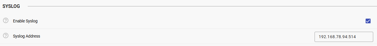
Enabling Syslog
The syslog feature is disabled by default. When enabled, the application sends formatted log messages to your specified syslog server containing information about:
-
Application startup and shutdown events
-
Input state changes and their sources
-
Communication status changes (loss and recovery)
-
Relay activation events and their triggers
-
Raw message data for protocol debugging
Syslog Server Configuration
Configure your syslog server by entering its IP address and port number in the format "192.168.1.50:514". The application uses standard syslog formatting and can integrate with most network monitoring and log management systems.
The syslog messages include timestamp information, device identification, and detailed event descriptions, making it easy to correlate events across multiple devices in your IO tunnel network.
Operational Behavior
Understanding how the IO Tunnel application operates in practice helps ensure successful deployment and troubleshooting when issues arise.
Message Protocol and Compatibility
The application uses a standardized UDP message format that ensures compatibility across different Barionet models and firmware versions. Each message contains two main components: timing information and input status data.
Current Protocol Format: Messages use the format "SSSSS,DDDDDDDDDDDD" where the first five digits represent the send interval and the following twelve digits represent the status of all available inputs (positions 1-4 for built-in inputs, positions 5-12 for UX8 inputs - on Barionet 100 inputs 5 to 8 are Relays 5 to 8).
Legacy Protocol Support: For backward compatibility with older installations, the application also accepts the legacy format "SSSSS,DDDDDDDD" with only eight input status digits. When receiving legacy messages, the system automatically interprets positions 5-8 as UX8 inputs 1-4, with UX8 inputs 5-8 defaulting to inactive status.
This backward compatibility ensures that existing Barionet 50 and 100 installations can communicate with newer M44 devices without requiring firmware updates or configuration changes.
Real-Time Operation
The IO Tunnel application operates with minimal latency to ensure responsive control. Input changes are detected within 100 milliseconds and transmitted immediately to the remote device. Similarly, incoming messages are processed immediately upon receipt, ensuring rapid relay response times.
Input Monitoring: The system continuously monitors all available inputs for state changes. When an input transitions from open to closed or closed to open, the change is detected, logged, and immediately transmitted to the configured remote device.
Relay Control: Incoming messages are processed immediately, with relay state changes occurring within milliseconds of message receipt.
UX8 Extension Handling
The application automatically detects whether a UX8 extension module is connected and adjusts its operation accordingly. This plug-and-play capability means you can add or remove UX8 modules without modifying the application configuration.
The application supports up to 1x UX8 connected the BM44 head-end.
Automatic Detection: During startup, the system probes for available GPIO devices and automatically discovers which inputs and relays are physically present. Missing devices are safely ignored, and the system operates normally with whatever hardware is available.
When you add or remove a UX8, reboot the Barionet so the detection of the IOs is updated correctly.
Configuration Examples
These practical examples demonstrate common IO Tunnel configurations and help illustrate how the various settings work together to create effective control systems.
Basic Two-Device Setup
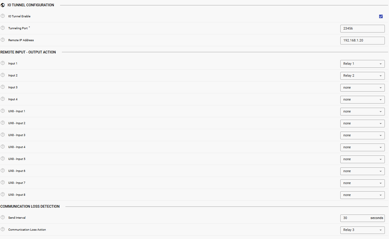
Consider a simple scenario where two Barionet M44 devices need to share input and output status. Device A (IP: 192.168.1.10) and Device B (IP: 192.168.1.20) should mirror each other's input states on their respective relays.
Device A Configuration:
-
IO Tunnel Enable: Yes
-
Tunneling Port: 23456
-
Remote Target Address: 192.168.1.20
-
Input 1 Trigger: Relay 1 (Remote Input 1 controls Local Relay 1)
-
Input 2 Trigger: Relay 2 (Remote Input 2 controls Local Relay 2)
-
Send Interval: 30 (Send status every 30 seconds)
-
Communication Loss Trigger: Relay 3 (Use Relay 3 as communication alarm)
Device B Configuration:
Use identical settings but change the Remote Target Address to 192.168.1.10. This creates a bidirectional link where inputs on either device control corresponding relays on the other device.
Operation: When Input 1 closes on Device A, Relay 1 on Device B immediately closes. Similarly, when Input 2 opens on Device B, Relay 2 on Device A immediately opens. Every 30 seconds, both devices send status updates to enable communication monitoring.
Software Disclaimer
IMPORTANT:
This software application ("Software") is provided "AS IS" without warranty of any kind, express or implied, including but not limited to the warranties of merchantability, fitness for a particular purpose, and non-infringement. In no event shall the author, developer, or distributor be liable for any claim, damages, or other liability, whether in an action of contract, tort, or otherwise, arising from, out of, or in connection with the Software or the use or other dealings in the Software.
Use at Your Own Risk: The user assumes all responsibility and risk for the use of this Software. The author makes no representations or warranties regarding the accuracy, reliability, completeness, or timeliness of the Software or its suitability for any particular purpose.
No Support Obligation: The provision of this Software does not create any obligation to provide technical support, maintenance, updates, enhancements, or modifications. The Software is provided for educational and reference purposes only.
Third-Party Dependencies: This Software may utilize third-party libraries and components. The user is responsible for ensuring compliance with all applicable licenses and terms of use for such dependencies.
Network and Security: The user is solely responsible for implementing appropriate security measures and network configurations. The author is not responsible for any security vulnerabilities, data breaches, or network disruptions that may result from the use of this Software.
Compliance: Users are responsible for ensuring that their use of this Software complies with all applicable laws, regulations, and organizational policies in their jurisdiction.
Limitation of Liability: Under no circumstances shall the total liability of the author exceed zero dollars ($0.00) for any damages arising out of or related to the use of this Software.
By using this Software, you acknowledge that you have read, understood, and agree to be bound by the terms of this disclaimer.