Annuncicom PS Touch 400 IC Paging Evo User Manual
Package content
PS Touch 400 device
Gooseneck condenser microphone
About this Manual
This manual gives a detailed explanation of the Barix IC Paging EVO firmware running on a Barix PS Touch 400 device and its Web Interface. The Barix PS Touch 400 device was used as a source example, but all Barix compatible devices will work accordingly (see more information below).
About IC Paging Evo
IC Paging Evo is a fully functional application for building intercom and paging systems over IP-based networks. IC Paging Evo merges Barix IC Paging and Simple Paging solutions into a single application where you can easily select the solution that best suits your needs. This way, PS Touch 400 Master Station, can easily be configured and become part of an IC Paging or Simple Paging system in just a few minutes, using as clients Exstreamer M400, MPA400, MR400, IP Former TPA400 and Annuncicom MPI400.
Although similar, IC Paging and Simple Paging applications have different features and can work differently depending on your needs. For the purpose of this manual, whenever the functions differ, they are shown in separate columns; common functions are shown in the same column.
For IC Paging and Simple Paging client support on legacy devices see IC Paging User Guide and Annuncicom PS Touch Simple Paging User Guide.
For IC Paging and Simple Paging client support on Exstreamer M400, MPA400, MR400, IP Former TPA400 and Annuncicom MPI400 see IP Audio Client user manual.
The communication between the master and the client components of the paging system is implemented using BARP (Barix Paging Protocol).
Annuncicom PS Touch 400 Description
Front panel
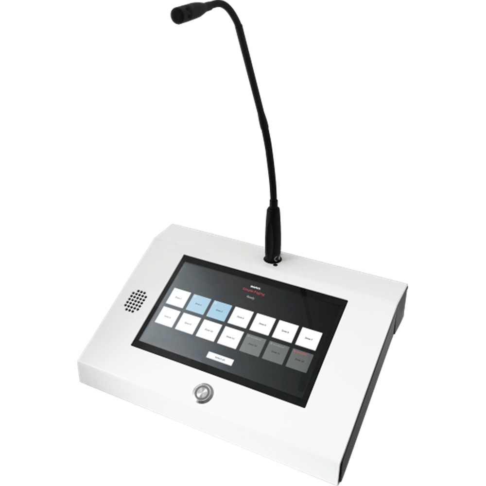
PS Touch 400: Front view
XLR gooseneck condenser microphone (included).
Color touch screen, 1024×600 pixel resolution.
5-Watt output speaker.
PTT (push-to-talk) button with LED ring.
Back panel
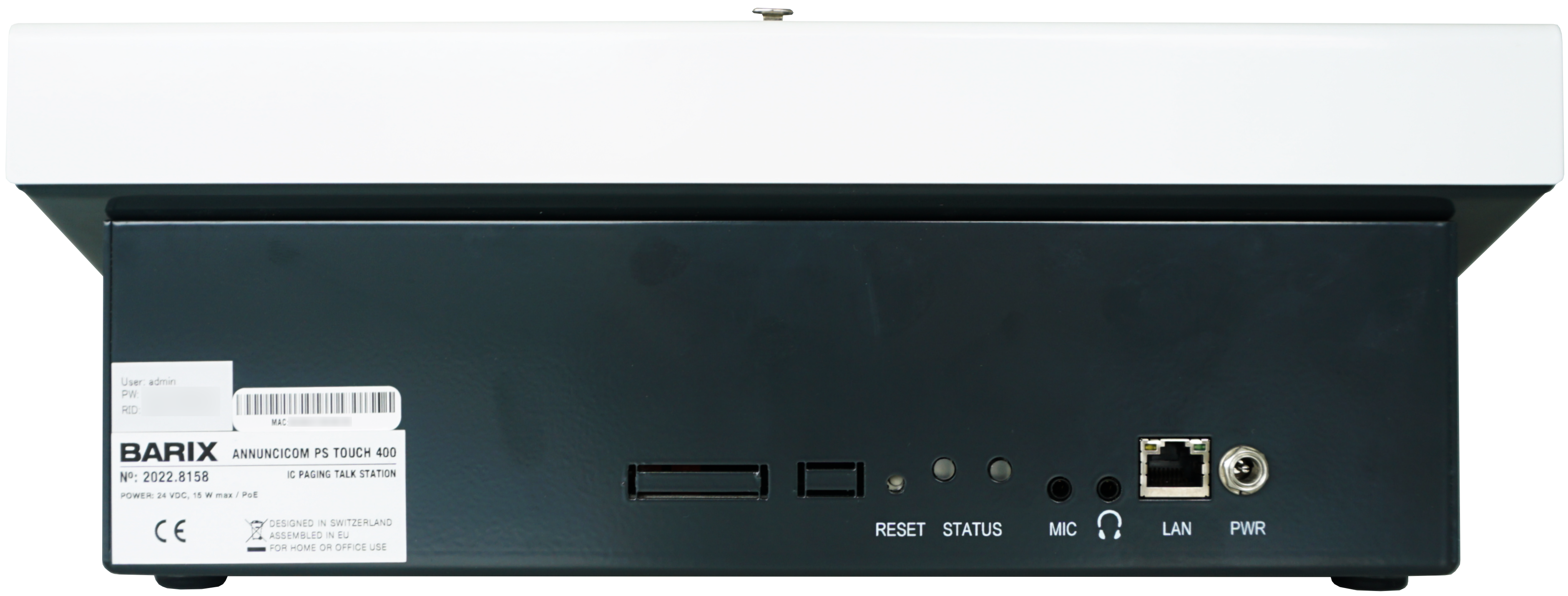
PS Touch 400: Rear view
RESET button: Use for the “Reboot” and “Reset to Factory Defaults” functions.
STATUS LEDS
MIC input: use to connect an external mic.
🎧 (Headphones output): Use to connect headphones.
LAN: Connect your LAN via a 10/100Mbps network connection, PoE (802.3af standard).
PWR: Connect a 24VDC, 15W power adapter (optional).
PS Touch 400 Setup
Attach the provided microphone to the connector located on the top of the device.
Connect the PS Touch to your PoE switch (or PoE adapter) using a regular Ethernet cable. If PoE is not available to power the device, use an optional 24VDC, 15W power adapter.
By default, the device is configured to run as a DHCP client. It will acquire an IP address at boot, and it will announce it through the built-in speaker.
Be ready to listen to the IP address announcement and note it.
You can also use the “Barix Discovery Tool” available here https://help.barix.com/tools/discovery-tool to find the PS Touch 400 IP address.
Booting
When shipped from factory, the PS Touch 400 default application is “Simple Paging”. During boot, the display shows the message: “Initializing the Simple Paging client”.
When the boot process ends, the message changes to: “Ready for paging”.
The display turns off after a few seconds of inactivity. Just touch it to turn it on again. Display inactivity timeout can be adjusted with the Web Interface. See “General Settings ➡️ Touch panel Settings”
In your web browser, enter the IP address you retrieved previously.
Login to the PS Touch 400 Web Interface using “admin” as username and the password printed on the back of the device and on the supplied stickers.
Web Interface
Home
IC Paging | Simple Paging |
|---|---|
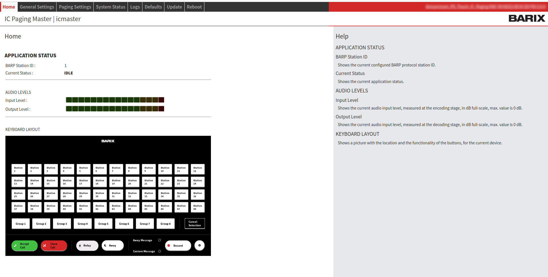 IC Paging: Home Page APPLICATION STATUS
AUDIO LEVELS
KEYBOARD LAYOUT: Shows a picture with the location and the functionality of the buttons, for the IC Paging application. | 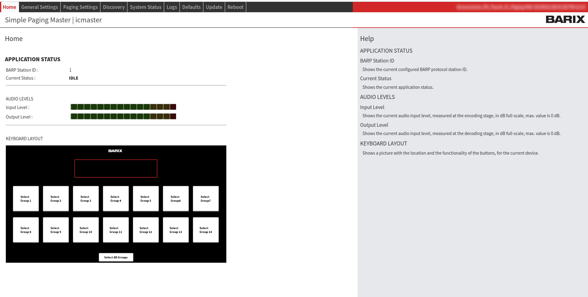 Simple Paging: Home Page APPLICATION STATUS
AUDIO LEVELS
KEYBOARD LAYOUT: Shows a picture with the location and the functionality of the buttons, for the Simple Paging application. |
PS Touch 400 Button Functions
IC Paging | Simple Paging | ||||||||||||||||||
|---|---|---|---|---|---|---|---|---|---|---|---|---|---|---|---|---|---|---|---|
Station 1 ➡️ Station 48: select the target station(s) to page. If it’s selected the 112 keys option (see below on Touch Panel Settings) the red arrow on top right opens a further page with Station 49 ➡️ Station 96 keys (ID 65 ➡️ ID 112). With the top left red arrow you can shift back to the main page. | Group 1 ➡️ Group 14: select to page the corresponding target Group(s). Buttons are colored according to the following Group configuration status.
| ||||||||||||||||||
Group 1 ➡️ Group 8: select to page the corresponding target Group(s). The assignment of these buttons is configured in the Web Interface ➡️ Paging Settings ➡️ Groups. | Select All Groups: select all Groups. | ||||||||||||||||||
Cancel Selection: clear current target/group selection. | PTT (Push-To-Talk) Button: the physical button under the display.
| ||||||||||||||||||
Accept Call: accept an incoming call. Light yellow (Active Call) when the call is accepted. | |||||||||||||||||||
Close Call: hang-up current call; pressing this key will also cancel an incoming call. | |||||||||||||||||||
Relay: triggers the connected client's relay (door open) for the Relay Activation Time if a call is in progress.
| |||||||||||||||||||
Away: enables/disables the Away and Call Reject “unattended” modes. When the Away mode is enabled, any client attempting to call the master will hear the recorded “Away Message”, after which the call is automatically terminated. To activate this mode:
In the Call Reject mode, instead of playing the unattended message or opening a call session, the master sends a special signal to the client indicating that it is unavailable. In this case the client should call the next master in its list. To activate this mode:
| |||||||||||||||||||
Away Message: allows to listen the unattended message locally. | |||||||||||||||||||
Custom Message: opens the messages tab (16 messages). Allows listening the selected message locally when there is no target selection. When targets are selected, the selected message is sent to the selected destination/s. | |||||||||||||||||||
Record: record Custom or Away messages.
| |||||||||||||||||||
⚙ (settings icon): use to access the “Single Target Buttons Name Configuration Page”.
| |||||||||||||||||||
PTT (Push-To-Talk) Button: the physical button under the display.
|
You MUST click the “Submit” button to apply any changes when configuring your device. Click the “Cancel” button to cancel changes and revert to the previous values..
General Settings
IC Paging | Simple Paging |
|---|---|
Device Alias | |
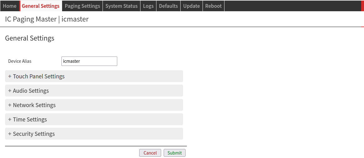 IC Paging/ Simple Paging: Alias Device Alias: Define an alias for the device. This is useful for distinguishing multiple devices on the same network and browse favorites. Need to reload page to view changes. | |
Touch Panel Settings | |
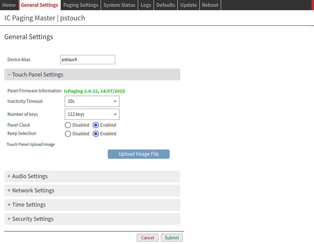 Panel Firmware Information: this field shows information about the touch panel firmware version and date. Inactivity Timeout: time after which the screen enters stand-by mode.
Number of keys: select the 64/112 keys panel layout. Panel Clock: shows a clock on the PS Touch 400 touchscreen, right above the text box. It is synchronized to the device time. The time zone can be configured from “Time Settings” section.
Keep Selection: after paging, the selected groups/client keys remains active.
Touch Panel Upload Image: upload a background JPG image to the touch panel.
Notes: Prepare the background image using your favorite picture tool (ex. PhotoShop, GIMP, Paint, etc) taking into account the following information.
| 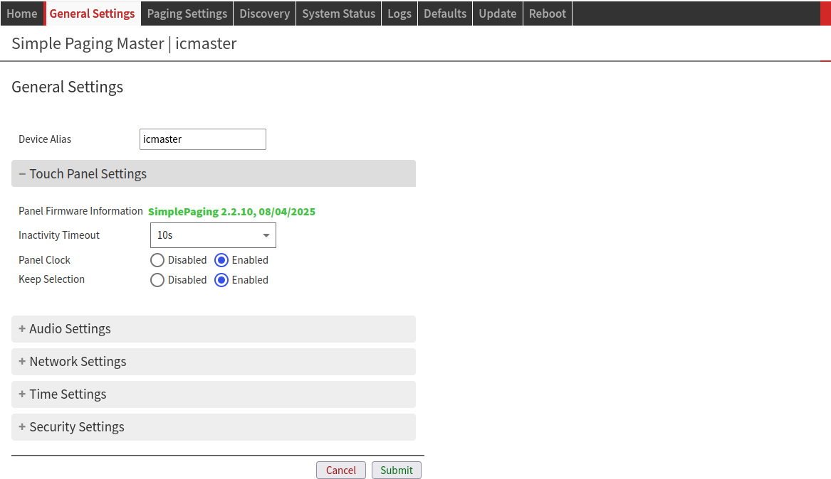 Simple Paging: Touch Panel Settings Panel Firmware Information: this field shows information about the touch panel firmware version and date. Inactivity Timeout: time after which the screen enters stand-by mode.
Panel Clock: shows a clock on the PS Touch 400 touchscreen, right above the text box. It is synchronized to the device time. The time zone can be configured from the “Time Settings” section.
Keep Selection: after paging, the selected groups/client keys remains active.
|
Audio Settings | |
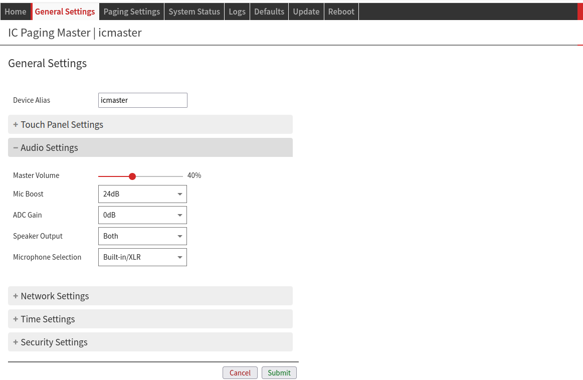 IC Paging/ Simple Paging: Audio Settings Master Volume: Set the main speaker volume.
Mic Boost: Set the value for “Mic Boost”
You might need to change this value when switching from internal (XLR) to external microphone. ADC Gain: Input audio range. It is additional to the Mic Boost.
Speaker Output: Select the speaker for audio output.
Microphone Selection: Select the microphone used for the audio input.
| |
Network Settings | |
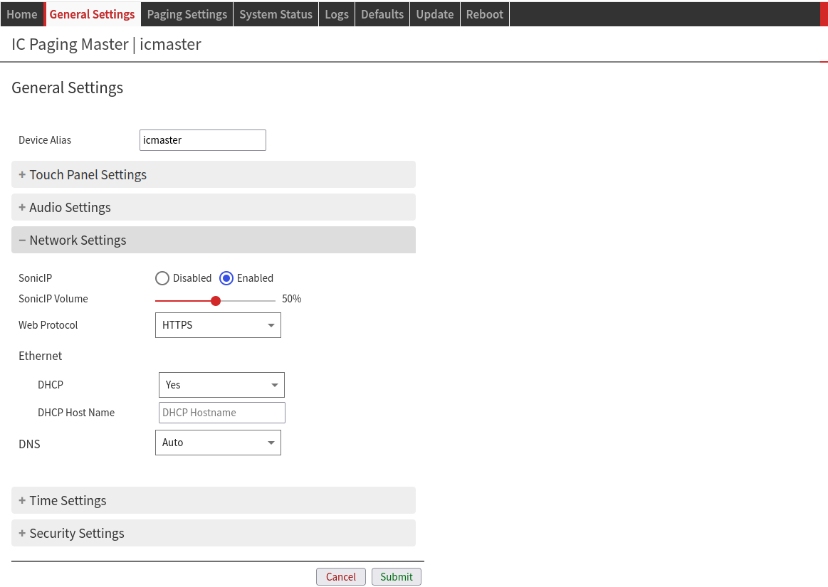 IC Paging/ Simple Paging: Network Settings SonicIP: when booting, the device announces its IP address through audio output.
SonicIP Volume: sets the volume at which the SonicIP will be announced at boot.
Web Protocol: changes the web communication protocol used.
After changing the protocol make sure to reload the page with the proper URL “http://” or “https://” Ethernet DHCP: “Dynamic Host Configuration Protocol” is used for automatic assignment of IP address, Netmask and Gateway.
DNS: select the method to define the “Domain Name System”.
| |
Time Settings | |
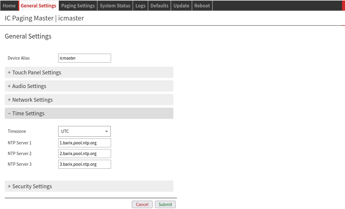 IC Paging/ Simple Paging: Time Settings Timezone: select the appropriate timezone/ region for the device from the drop-down list.
NTP Server 1, 2, 3: you can set up to 3 “Network Time Protocol” servers for Internet time adjustment.
| |
Security Settings | |
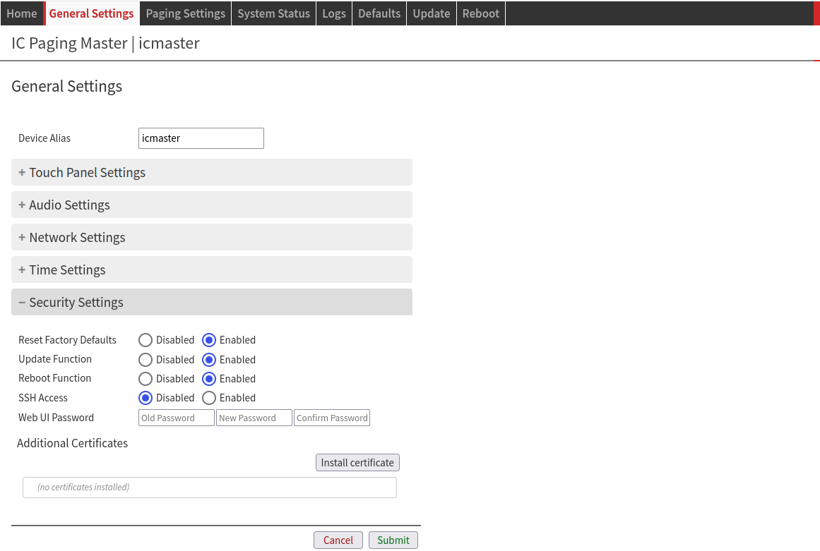 IC Paging/ Simple Paging: Security Settings Reset factory defaults: disable or enable the “Reset Factory Defaults” function from both Web Interface “Defaults” tab and from the device RESET button.
Update function: disable or enable the Update function from the Web Interface tab.
Reboot Function: disable or enable the “Reboot” function from the Web Interface “Reboot” tab.
SSH Access: disable or enable SSH protocol access. This might be useful in some support cases. Enable it only when Barix support asks you to do so. Leave it disabled to avoid having the device listening on the SSH port while operating.
Web UI password: This group of fields is visible as long as no password is set.
Additional Certificates: Install additional Certificates (.crt file) that might be required to secure the connection with the device:
| |
Paging Settings
IC Paging | Simple Paging |
|---|---|
Application | |
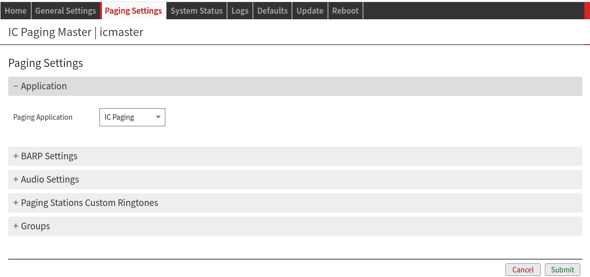 IC Paging/ Simple Paging: Paging Application Paging Application: Select the paging application you want to use from the dropdown list.
Changing the application type forces a panel firmware update. This can take a considerable amount of time to complete. Please be patient when doing it. | |
BARP Settings | |
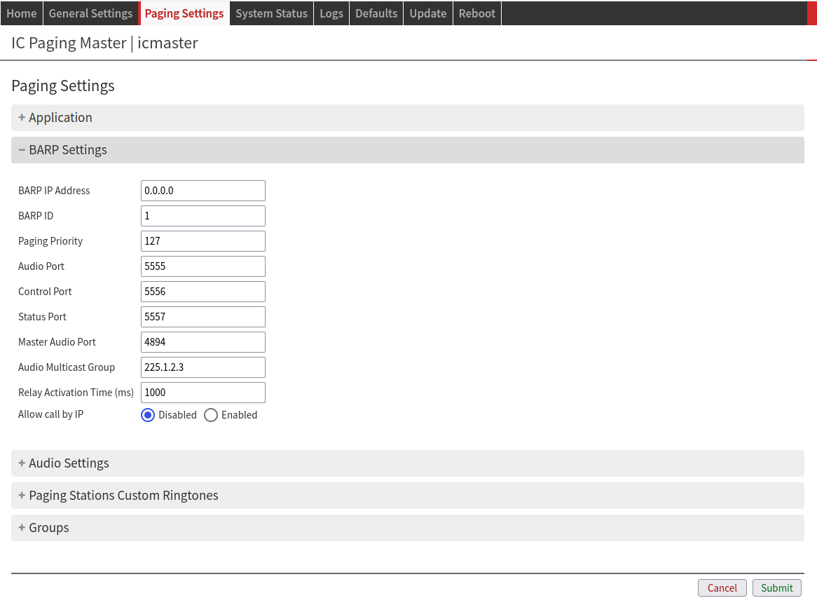 IC Paging: BARP Settings BARP IP Address: If set to 0.0.0.0 or an invalid multicast address, then BARP messages are broadcasted. In any other case, BARP messages are multicasted.
BARP ID Paging master ID number as visible to clients and masters on the network.
Paging Priority: Enter the priority of the audio messages sent by the master station.
Audio Port: Sets the UDP port at which paging audio packets will be sent. It is overwritten by Master Audio Port (if configured). Clients should be configured with the same port.
Control Port: Sets the UDP port to which all control messages from the master will be sent. Clients should be configured with the same port.
Status Port: Sets the UDP port at which all status messages from clients/masters are received. All clients and masters should be configured with the same port.
Master Audio Port: Sets the port to be used when paging audio. If set to “0” the “BARP Audio Port” will be used.
Audio Multicast Group: Multicast group address for paging the audio.
Relay Activation Time (ms): Sets the time duration (ms) for the relay activation. This time is sent to the client.
Allow call by IP
| 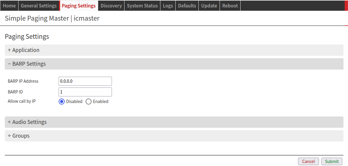 Simple Paging: BARP Settings BARP IP Address: If set to 0.0.0.0 or an invalid multicast address, then BARP messages are broadcasted. In any other case, BARP messages are multicasted.
BARP ID Paging master ID number as visible to clients and masters on the network.
|
Audio Settings | |
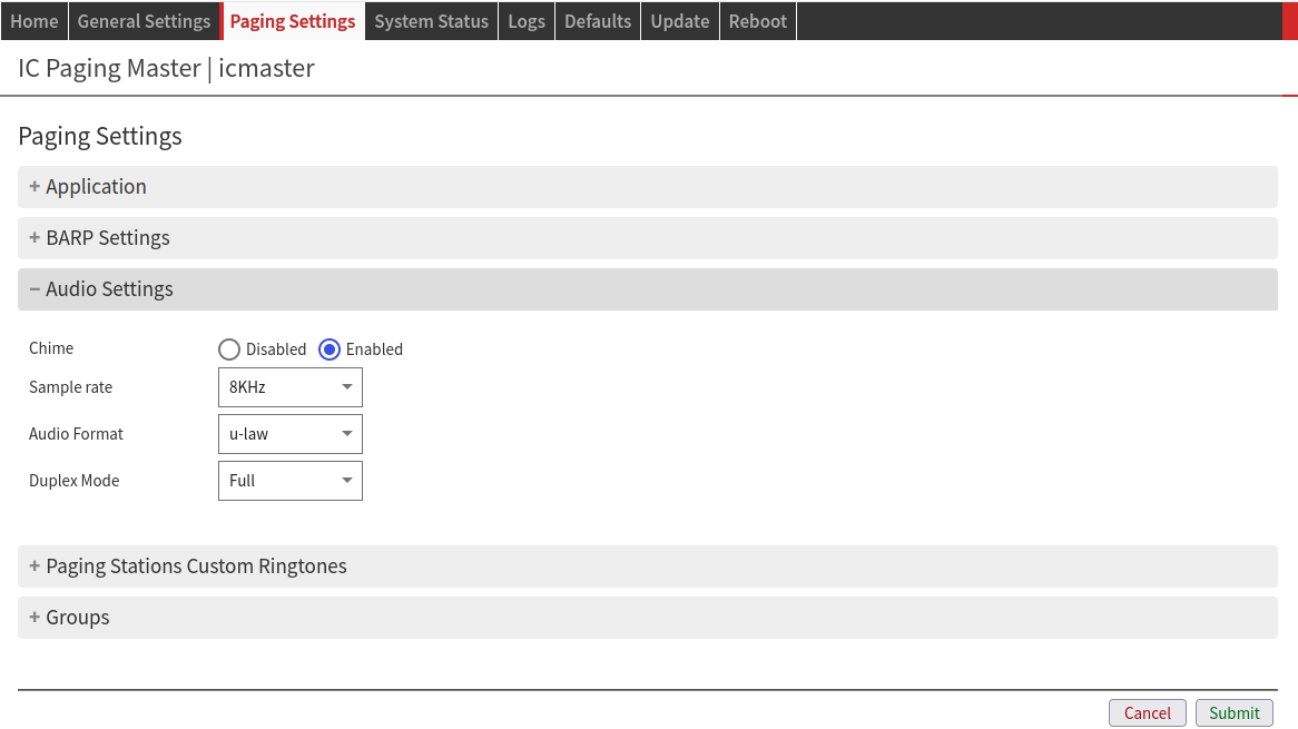 IC Paging: Audio Settings Chime: Plays a short tone before paging starts.
Sample Rate: Frequency of audio capture and playback.
Audio Format: Codec of capture and playback.
Duplex Mode: Choose the desired mode of operation for paging.
| 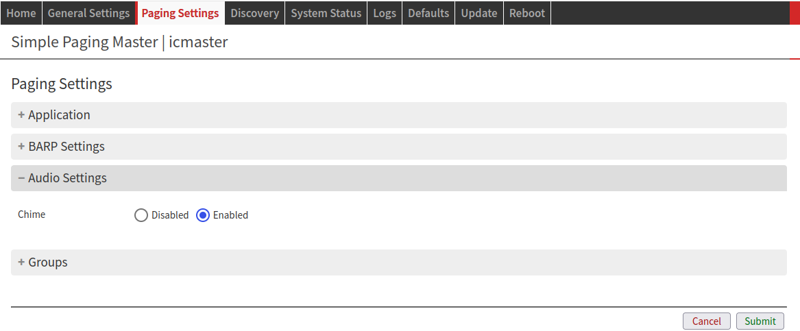 Simple Paging: Audio Settings Chime: Plays a short tone before paging starts.
|
Paging Stations Custom Ringtones | |
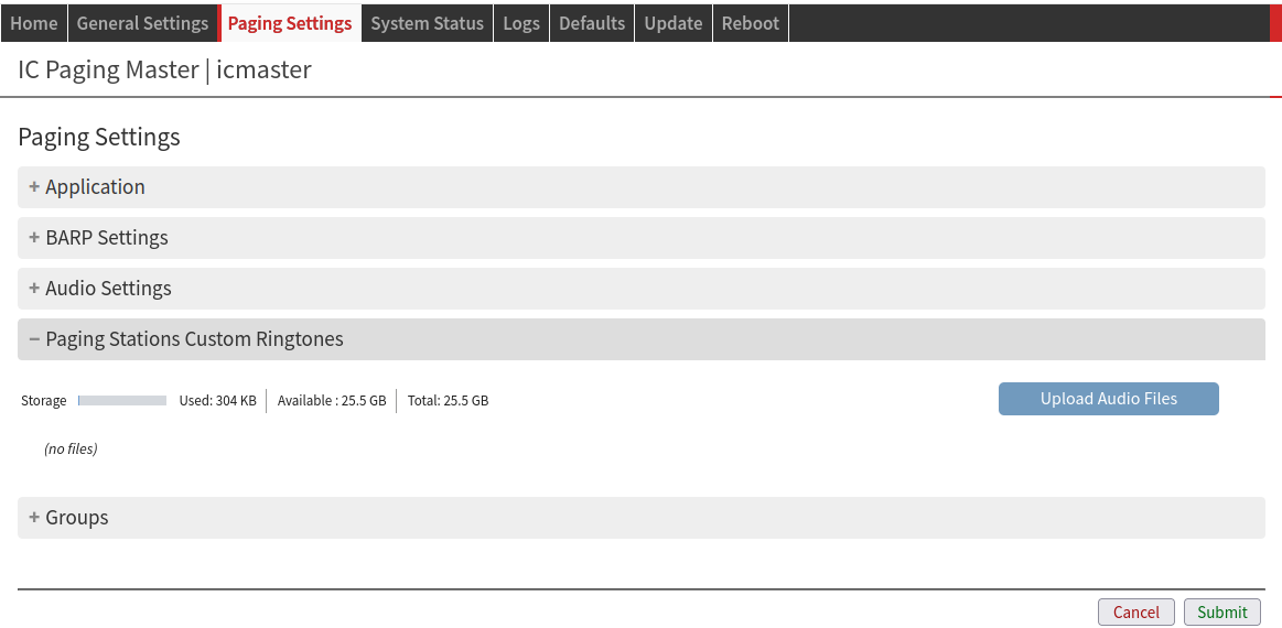 IC Paging: Custom Ringtones You can upload audio files to a paging station. These will be available to play as a “Local File”.
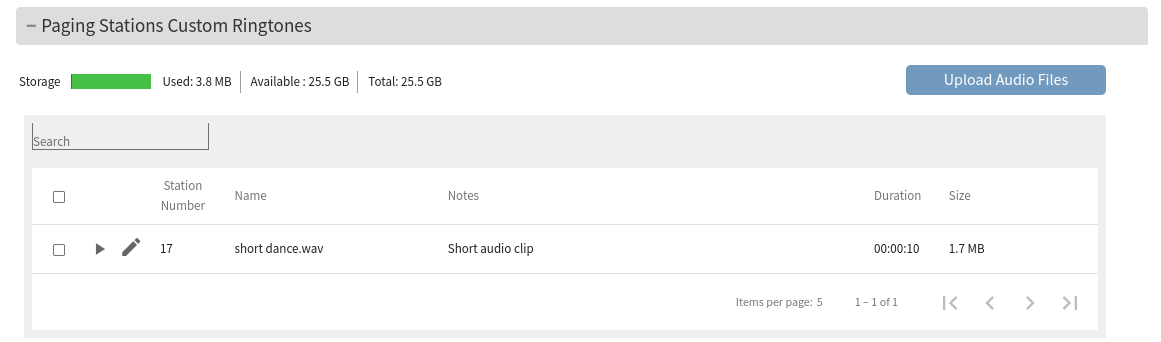 IC Paging: Custom Ringtones Upload
Please take in consideration:
| (N/A) |
Custom Message Files | |
You can upload audio files to a paging station. These will be available to play as a “Local File”.
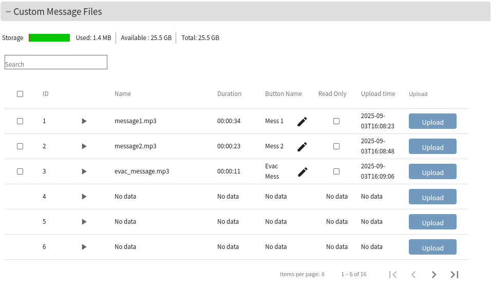 IC Paging: Custom Messages Upload
Please take in consideration:
| (N/A) |
Groups | |
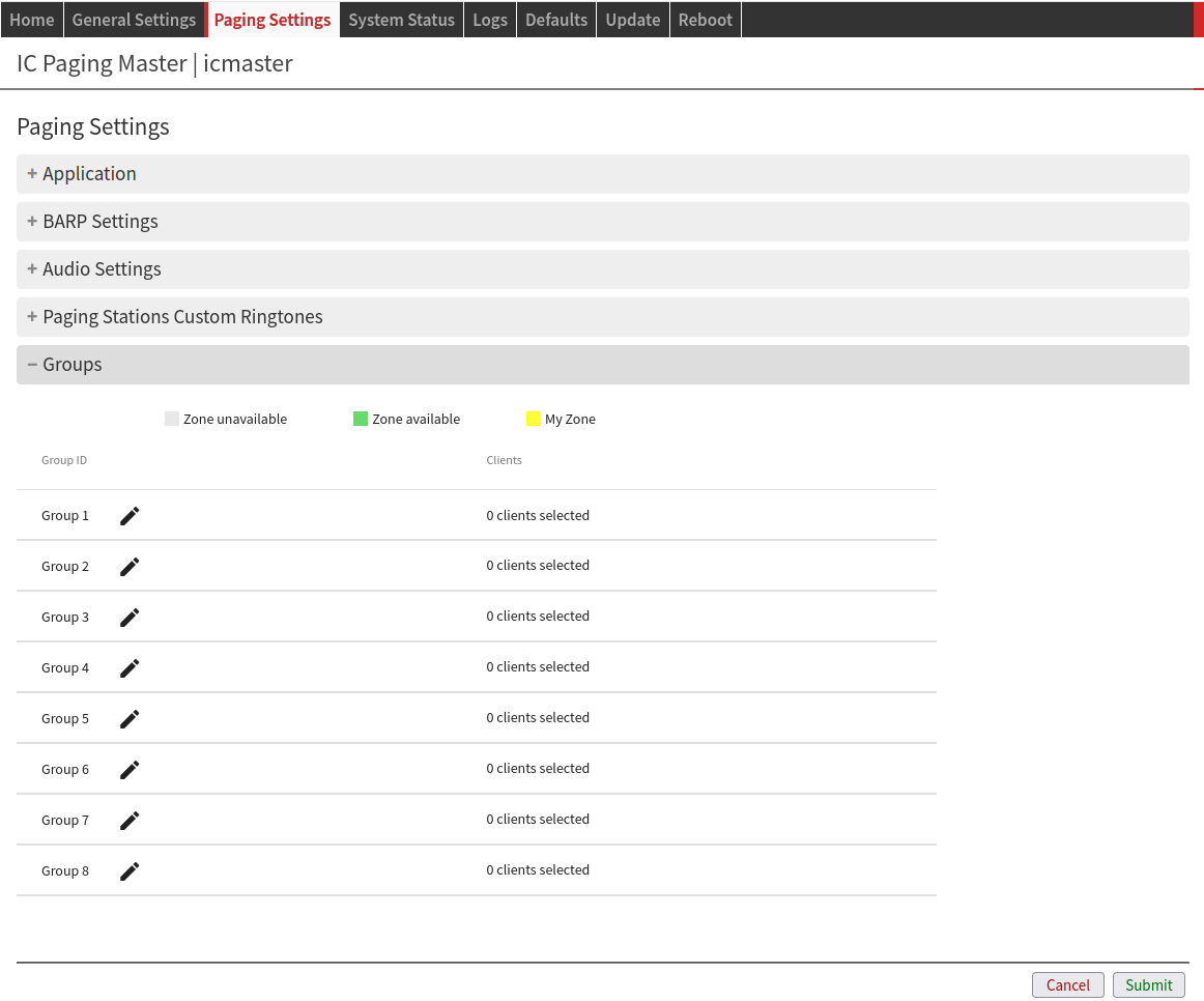 IC Paging/ Simple Paging: Groups In this window, you can configure your paging Groups - 8 Groups for IC Paging, 14 Groups for Simple Paging. Each Group can page 128 clients. Click on the Group number you want to configure. You can see paging zones described as:
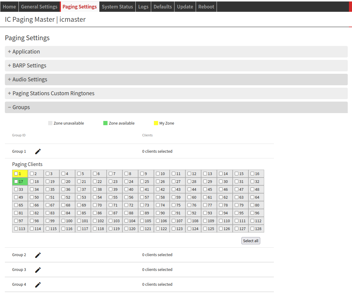 IC Paging/ Simple Paging: Group Configuration To configure a Group, click the station ID numbers you want to include in the Group to select them. Click again to deselect. You can also change the Group name if needed:
The Group name changes will only apply to the PS Touch 400 display after submitting. | |
Discovery
IC Paging | Simple Paging |
|---|---|
(N/A) | 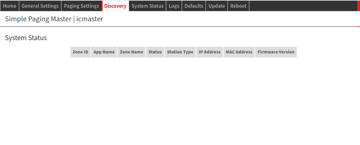 Simple Paging: Discovery This page shows the components of the Simple Paging system that have responded to this device.
Devices are remembered and only forgotten on reboot. A device that is no longer in the system will be displayed here as unavailable until reboot. |
System Status
IC Paging | Simple Paging |
|---|---|
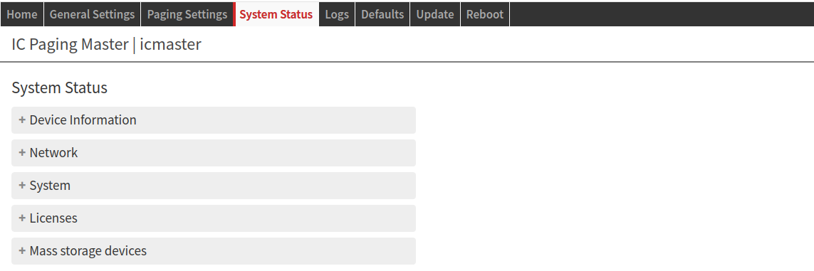 IC Paging/ Simple Paging: System Status This is a general information page about your System Status. Click the + icon to expand fields and see information about:
| |
Logs
IC Paging | Simple Paging |
|---|---|
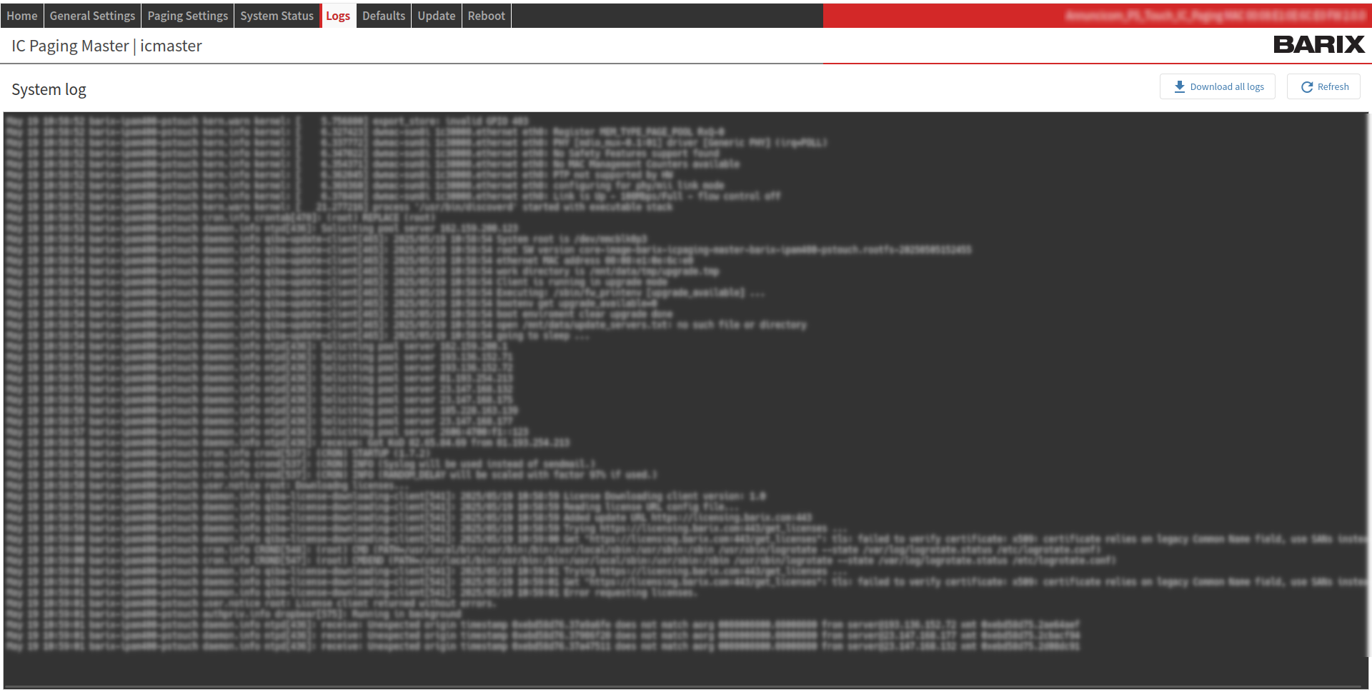 IC Paging/ Simple Paging: Logs In this page you can check device logs. Click the “Download all logs” button to create a log file on your local drive. Click the “Refresh button” to refresh the screen. | |
Defaults
IC Paging | Simple Paging |
|---|---|
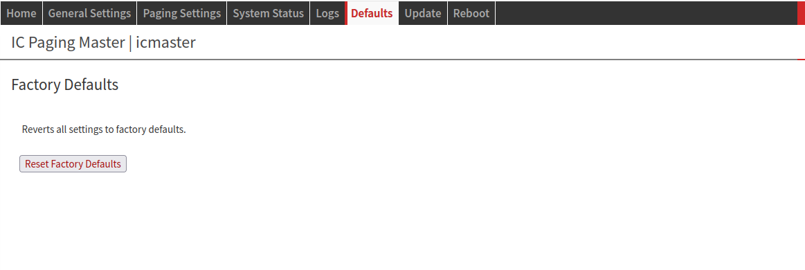 IC Paging/ Simple Paging: Defaults Click the “Reset Factory Defaults” button to revert all settings except “Network settings” to the factory defaults. A local user can completely reset the device to factory defaults (hardware reset), including Network settings, by pressing the RESET button of the device during approximately 10 seconds.
| |
Update
IC Paging | Simple Paging |
|---|---|
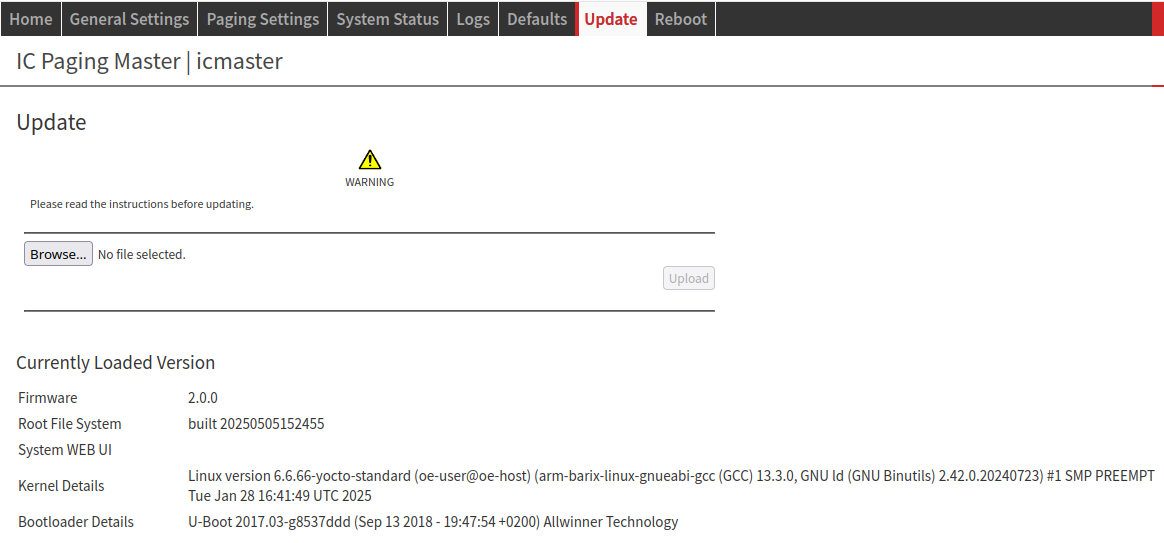 IC Paging/ Simple Paging: Update Please read the instructions before updating.
This operation can take several minutes. Do not interrupt the update process nor power off the device while updating to avoid permanent damage.
If the "Reset" function is disabled from the Security Settings page the message “ Update function is currently disabled” is displayed. Currently Loaded Version: | |
Reboot
IC Paging | Simple Paging |
|---|---|
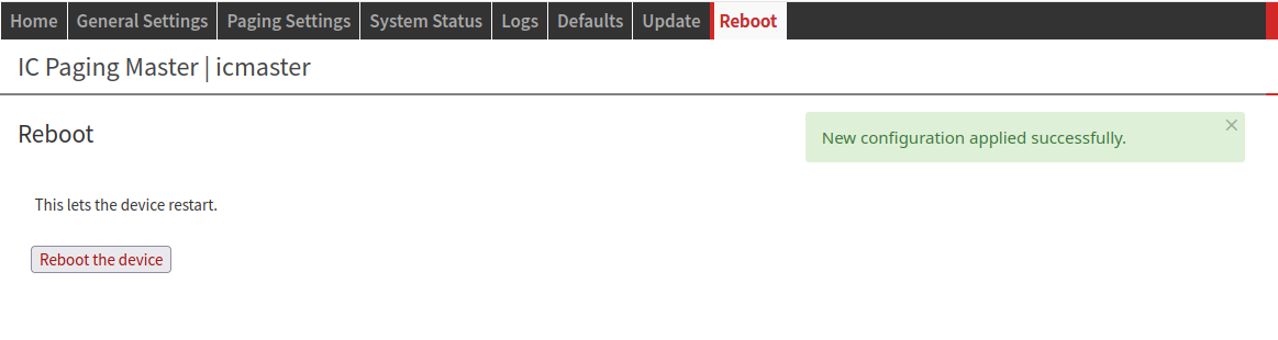 IC Paging/ Simple Paging: Reboot Click the "Reboot the device" button to restart the device. A local user can also reboot the device by pressing shortly the "RESET" button of the device.
| |
Editing keys (IC Paging)
On IC Paging you can move and hide/show some of the screen buttons.
To activate the key editing mode touch an empty space on the touch panel, and hold it for 5 seconds.The “Edit mode! Long press (5s) to save changes, 20s to
restore to panel defaults” message will appear on the screen.To move a button, just touch it and move it around.
To hide a button, just touch and hold (without moving) it for 3 seconds. The button will be shown with 40% brightness, meaning that it will be hidden when the
changes are saved.To unhide a button, just press and hold a button with reduced brightness until it shows with 100% brightness.
To save the changes, touch the screen on a free space, and hold it for 5 seconds.
The buttons configuration will be stored on the device, and reloaded after a successful start.If you are using 2 pages of buttons, pleas configure the buttons of the first page, and store it. Then switch to the second page by clicking on the red off-page
connector (shown only if you have configured that you are using 2 pages of buttons from the web UI), and configure them the same way.To restore the original configuration, touch the screen on a free space and hold it for 20 seconds.
Compliance and further Information
This equipment has been tested and found to comply with the limits for a Class B digital device, pursuant to part 15 of the FCC Rules. These limits are designed to provide reasonable protection against harmful interference in a residential installation. This equipment generates, uses and can radiate radio frequency energy and, if not installed and used in accordance with the instructions, may cause harmful interference to radio communications. However, there is no guarantee that interference will not occur in a particular installation. If this equipment does cause harmful interference to radio or television reception, which can be determined by turning the equipment off and on. The user is encouraged to try to correct the interference by one or more of the following measures:
Reorient or relocate the receiving antenna.
Increase the separation between the equipment and receiver.
Connect the device into an outlet on a circuit different from that to which the receiver is connected.
Consult the dealer or an experienced radio/TV technician for help.
Safety and precaution recommendations apply. Find them in the download section at http://www.barix.com

Find your distributor on this list for more hardware.
For questions that are extending the documentation, feel free to contact us on:
International: +41 434 33 22 22
USA: +1 866 815 0866
Email: support@barix.com
All information and the use of this product including all services are covered under the Barix Terms & Conditions and our Privacy Policy. Please follow the Safety and Precaution Recommendations. Barix is a ISO 9001:2015 certified company. All rights reserved. All information is subject to change without notice. All mentioned trademarks belong to their respective owners and are used for reference only.