Introduction
The aim of this document is to guide the user through the functionalities of the IP Audio Client application, which is the software running on the following Barix Products:
|
PRODUCT |
ORDERING PART NUMBER |
DESCRIPTION |
|
Exstreamer M400 |
2020.9291 EU Package 2020.9292 US Package 2020.9293 UK Package 2020.9294 No PSU Package |
IP Audio Decoder with stereo line level audio output on RCA connectors |
|
Exstreamer M400 InformaCast |
2020.9295 EU Package 2020.9296 US Package 2020.9297 UK Package 2020.9298 No PSU Package |
IP Audio Decoder with stereo line level audio output on RCA connectors - Including Singlewire’s InformaCast license |
|
Exstreamer M400 Dante® |
2023.9403P EU Package 2023.9404P US Package 2023.9405P UK Package 2023.9406P NoPSU Package |
IP Audio Decoder with stereo line level audio output on RCA connectors - Including Dante® license |
|
Exstreamer M400 Dante® + InformaCast |
2023.9407P EU Package 2023.9408P US Package 2023.9409P UK Package 2023.9410P NoPSU Package |
IP Audio Decoder with stereo line level audio output on RCA connectors - Including Dante® license + Singlewire’s InformaCast license |
|
Exstreamer MPA400 |
2020.9317P Package |
IP Audio Decoder, PoE or externally powered with up to 40W amplified output on screw terminal block to drive loudspeakers |
|
Exstreamer MPA400 InformaCast |
2020.9325P Package |
IP Audio Decoder, PoE or externally powered with up to 40W amplified output on screw terminal block to drive loudspeakers - Including Singlewire’s InformaCast license |
|
Exstreamer MPA400 Dante® |
2023.9411P Package |
IP Audio Decoder, PoE or externally powered with up to 40W amplified output on screw terminal block to drive loudspeakers - Including Dante® license |
|
Exstreamer MPA400 Dante® + InformaCast |
2023.9412P Package |
IP Audio Decoder, PoE or externally powered with up to 40W amplified output on screw terminal block to drive loudspeakers - Including Dante® license + Singlewire’s InformaCast license |
|
Exstreamer MR400 |
2023_9418P Package |
IP Audio Decoder, 24VDC externally powered with up to 1W amplified output, one relay |
|
Exstreamer MR400 InformaCast |
2023_9431P Package |
IP Audio Decoder, 24VDC externally powered with up to 1W amplified output, one relay - Including Singlewire’s InformaCast license |
|
Exstreamer MR400 Dante® |
2023_9432P Package |
IP Audio Decoder, 24VDC externally powered with up to 1W amplified output, one relay - Including Dante® license |
|
Exstreamer MR400 Dante® + InformaCast |
2023_9433P Package |
IP Audio Decoder, 24VDC externally powered with up to 1W amplified output, one relay - Including Dante® license + Singlewire’s InformaCast license |
|
IP Former |
2020.9299P Package |
IP Audio Decoder, PoE powered with up to 6W amplified output on screw terminal block to drive loudspeakers |
|
IP Former InformaCast |
2020.9301P Package |
IP Audio Decoder, PoE powered with up to 6W amplified output on screw terminal block to drive loudspeakers - Including Singlewire’s InformaCast license |
|
IP Former Dante® |
2023.9401P Package |
IP Audio Decoder, PoE powered with up to 6W amplified output on screw terminal block to drive loudspeakers - Including Dante® license |
|
IP Former Dante® + InformaCast |
2023.9402P Package |
IP Audio Decoder, PoE powered with up to 6W amplified output on screw terminal block to drive loudspeakers - Including Dante® license + Singlewire’s InformaCast license |
|
Annuncicom MPI400 |
2021.9330P Package |
IP Audio Encoder and Decoder, PoE power with up to 1W amplified output, balanced audio out, 3x audio inputs, digital inputs and relays |
|
Annuncicom MPI400 InformaCast |
2022.9372P Package |
IP Audio Encoder and Decoder, PoE power with up to 1W amplified output, balanced audio out, 3x audio inputs, digital inputs and relays - Including Singlewire’s InformaCast license |
|
Annuncicom MPI400 Dante® |
2023.9413P Package |
IP Audio Encoder and Decoder, PoE power with up to 1W amplified output, balanced audio out, 3x audio inputs, digital inputs and relays - Including Dante® license |
|
Annuncicom MPI400 Dante® + InformaCast |
2023.9414P Package |
IP Audio Encoder and Decoder, PoE power with up to 1W amplified output, balanced audio out, 3x audio inputs, digital inputs and relays - Including Dante® license + Singlewire’s InformaCast license |
|
Annuncicom AHE YA404 |
2025.9463P Package |
IP Audio Intercom Station, 24VDC, with (16x) 25/70V intercom station connections (2/4 wires). |
|
Annuncicom AHE YA404 InformaCast |
2025.9464P Package |
IP Audio Intercom Station, 24VDC, with (16x) 25/70V intercom station connections (2/4 wires) - Including SingleWire’s InformaCast license |
|
Annuncicom AHE YA404 Dante® |
2025.9465P Package |
IP Audio Intercom Station, 24VDC, with (16x) 25/70V intercom station connections (2/4 wires) - Including Dante® license |
|
Annuncicom AHE YA404 Dante® + InformaCast |
2025.9466P Package |
IP Audio Intercom Station, 24VDC, with (16x) 25/70V intercom station connections (2/4 wires) - Including Dante® + SingleWire’s InformaCast license |
Throughout this document these devices are referred to as IPAC devices
The document describes the elements and the functionalities of the application in detail. It doesn't cover arguments related to the physical connections of the IPAC devices, delegating this description in the Quick Install Guide of each one of them.
Dante® is a technology developed and owned by Audinate Pty Ltd - Any reference throughout the manual have the sole purpose of educating the user of IPAC in how to integrate with the Dante®.
What is IP Audio Client?
IP Audio Client is a flexible application that controls the audio play-out of the devices on which it runs. It allows the possibility to set up multiple "sources" from where getting the audio and organize them in a multi-layer priority hierarchy, meaning that the source with an higher priority will always play over sources with lower priority.
Thus IP Audio Client serves multiple application needs, it can work as:
-
a mass-emergency notification endpoint
-
a background music player with embedded scheduling functions
-
a paging endpoint
-
a RTP decoder
-
a VoIP / SIP endpoint
-
a pre-recorded message player
-
a Dante® receiver, transmitter and gateway device
Standard player
IP Audio Client can be configured to run in 3 modes:
-
Standard mode
-
AES67 mode
-
Dante Exclusive mode
One mode excludes the other, meaning that if the application is set to operate in "IP Audio Client" mode it cannot work in AES67 mode nor Dante mode. For this reason the entire user manual on AES67/Dante is detached from this manual, which describes solely the IP Audio Client application mode.
IP Audio Client Certified for Mass Emergency Notifications
IP Audio Client is a certified Intrado SynApps Revolution endpoint
IP Audio Client is a certified SingleWire InformaCast endpoint
About this manual
This manual is intended for distributors, installers and end users of the IP Audio Client solution. It will cover first configuration steps plus details on how to use the applications after the installation.
This manual assumes that the firmware version installed on the IPAC devices is the latest one released. (check out the release notes for information on the release history and change log). Barix always recommends to run the latest firmware available and provides a dedicated download area for registered users on www.barix.com/downloads.
IP Audio Client offers the possibility to update its firmware locally from its web user interface (more details in the Update Page section).
Additional support material
The following additional documents are available for the IP Audio Client application:
-
Beside checking regularly the Barix website and the Barix help, the user has access to support in several ways:
-
Check with your local distributor for the technical support they offer. A list of distributors is also available on the Barix website at this link
-
Email directly a Barix support technicians at support@barix.com
-
Quick Start
All IPAC devices offer the possibility to connect to the network via ETH (Ethernet) wired interface (10/100Mbps). If the IPAC device supports PoE, this is the only cable required to get the device powered, otherwise you would need to power the device using an external power supply.
IP Audio Client, by default, is configured to be a DHCP client, it acquires an IP address from a DHCP server reachable in the network.
The first configuration of the device involves the following steps:
|
1 |
Make all the necessary connections: audio, network and then power up the unit |
|
2 |
During boot the device will announce its IP Address (Sonic IP function), make sure to hear the audio on the output and note the IP address on paper. An IPAC device takes between 40s to 50s to finish the boot process depending on the hardware on which is running |
|
3 |
Connect to the IP Address of the device via web browser by typing in the URL the IP address just heard or type in the browser “http://barix-<MACLast6Digits>.local” (e.g. “http://barix-09c2a1.local”) |
|
4 |
Enter username and password (username: admin - password: printed on the backside of the device) - After login, please change the default password immediately under SECURITY in the Settings Page and make sure to store it in a safe place! 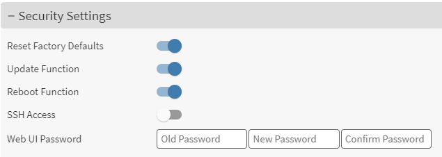
|
|
5 |
Locate the SOURCES tab. ENABLE any one of the sources and select the type of Source desired among the available ones. To enjoy the best music over internet simply play Barix Radio 🙂 which is a pre-configured source type available in the drop down 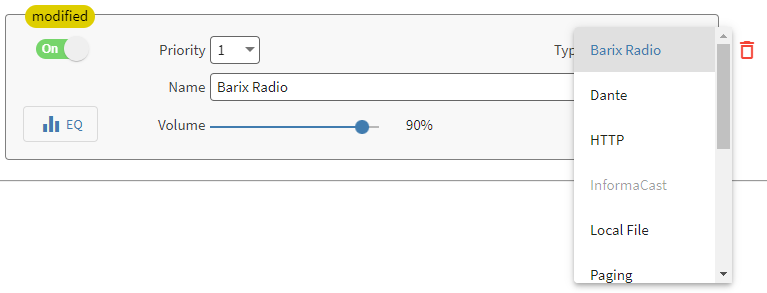
|
|
6 |
Click SUBMIT - After a few seconds the music starts 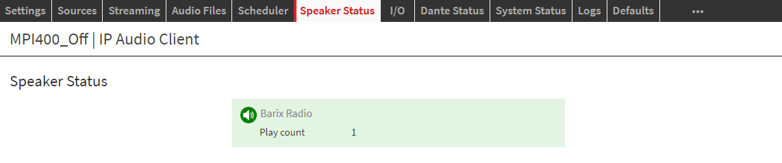
|
This was a quick start chapter to get the device up and running in less than 5 mins playing background music. The rest of the manual details every function available within the application.
Connect to the device
In this chapter are detailed all the methods that can be used to retrieve an IPAC device IP Address.
Retrieve the IP address using the Sonic IP® function
All Barix devices are equipped with a function called “Sonic IP®”, meaning that when you boot the device and this is connected to a network where a DHCP server is present, the device will acquire an IP address and announce it over its audio output. This function is useful when you connect to the device for the first time and need to access its web interface for performing the first configuration.
IMPORTANT: Before connecting to the amplification system, make sure the volume of your system is lowered at minimum or completely switched off to avoid potential damage to the system.
Follow the below steps to take advantage of the SonicIP function:
-
Connect the audio output to the receiving system, this varies depending on the IPAC device being used
-
Make sure the receiving system works fine so that when the IPAC device boots you are able to hear the IP Address
-
Power up the device. If the IPAC device supports PoE, this is the only cable you need
-
After 20s listen to the Sonic IP® announced and note it somewhere
-
After 35s the device is ready
Retrieve the IP address using the Discovery Tool
Other than the Sonic IP® function, there are other ways to find out a Barix device’s IP address. One is by using the Discovery Tool from Barix.
The Discovery Tool is freely available for download from www.barix.com/downloads.
The Discovery Tool is written in the Java programming language, so it requires a Java Runtime Environment (JRE) installed on your computer. If you do not have a JRE installed, you can download and install it from: https://www.java.com/en/download/ Java run time environments are available for many major operating systems. If you are running the Discovery Tool on a Linux or UNIX platform, the Discovery Tool also requires the X-window graphical user interface.
The Discovery Tool is distributed in a Java Archive (.jar) file. On most operating systems you can run the Discovery Tool by simply double-clicking on the discover.jar file. When the discovery tools open it will show the following interface:
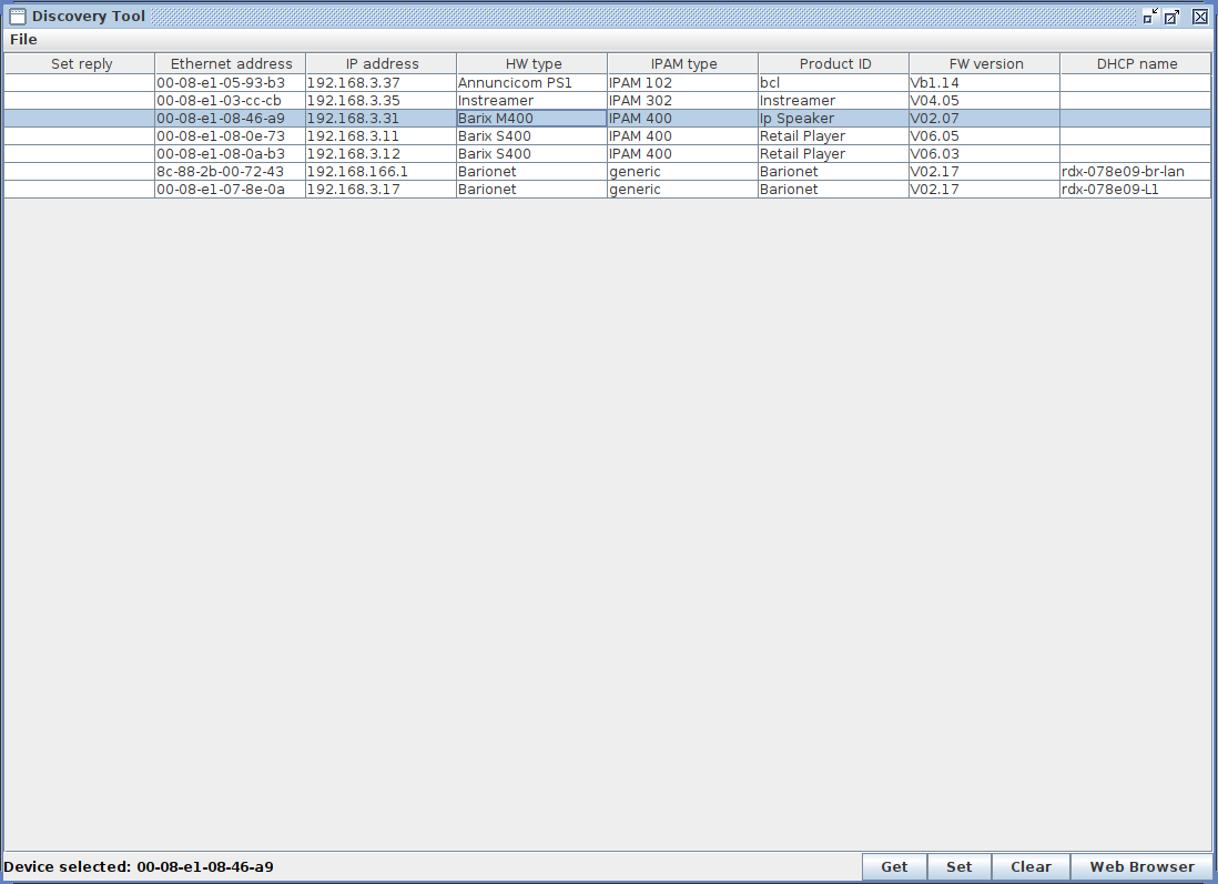
Click the "Get" button to initiate a search. The program will scan the network and list all the Barix devices found with its current IP address, MAC address (labeled "Ethernet Address" in the Discovery Tool), firmware version, and other information. The Discovery Tool will find any device that is on the same network as the computer running the tool, regardless of their current IP address setting. The tool will not search through a router to another subnet. Use the address that appears in the Discovery Tool to access the IPAC device via a web browser.
Setting a static IP Address using the Discovery Tool
-
In the discovery tool window Double click the IP Address field of the device which you want to change set the Static IP Address
-
Enter the IP address you want to assign.
-
Click SET in the lower right corner - the tool will reply with a “No error” in the “Set reply” column.
-
Reboot your device and access the web interface through the newly assigned IP Address. Make sure to finalize the network settings configuration (Subnet, Gateway, DNS), otherwise the device might not work correctly.
Connect using the mDNS/DNS-SD hostname
Every IPAC device comes with Avahi zero conf service enabled by default. One of the feature of Avahi is that it provides a default hostname to the device which can be solved to an IP Address in a local area network. With this is possible to access the web interface of IPAC without knowing the IP Address of the same. Simply type the following in your browser URL: “http://barix-<MACLast6Digits>.local” (e.g. “http://barix-09c2a1.local”).
NO DHCP REACHABLE
When the device boots for the first time and there is no DHCP reachable the unit cannot be used on the network. It will assign itself the placeholder IP address 0.0.0.0 (which doesn’t allow the usage of the unit on the network).
The boot process takes longer when this condition presents because the device tries multiple times to reach the DHCP server before executing the application.
The first time a device is powered it needs to find a DHCP server.
Application Settings
With the IP address or the hostname of the device is possible to connect to the web interface served by the the web server of any IPAC device.
Open a web browser and type the IP address or the hostname of the device in the URL field.
Default Password
By default new devices or devices that are accessed after a reset to defaults (soft or hard) will ask for credentials to login:
user: admin
password: printed on the back-side of the device
MAKE SURE TO CHANGE THE DEFAULT PASSWORD AFTER THE FIRST LOGIN AND STORE IT IN A SAFE PLACE
USE A PASSWORD WITH AT LEAST 10 CHARACTERS INCLUDING SPECIAL CHARACTERS, NUMBERS, LOWERCASE AND UPPERCASE LETTERS.
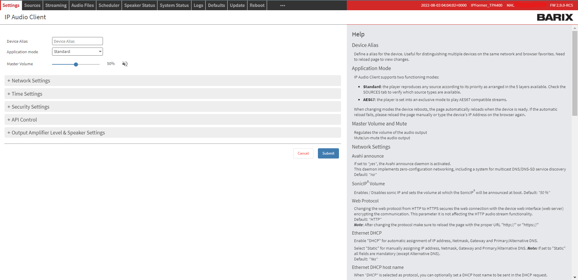
The settings page offers: network settings, time settings, security settings, API control settings and for IPAC devices with a built-in amplifier the possibility to set the power source and speaker settings.
The window is organized in:
-
The top navigation bar. In addition on the top right corner there are the MAC address and current firmware installed on the device
-
The operational area. Where the user input values and set parameters
-
The help section on the left side of the window
Main application controls

|
Item |
Description |
|---|---|
|
Name |
In the top bar it is visualized the name of the Firmware and the "Device Alias" |
|
Device alias |
A custom name that can be assigned to the device. This name shows up also in the remote configuration tool Default value is: " " |
|
Application mode |
Select the main application mode between Standard, AES67 and Dante exclusive mode (only licensed devices) Default value is: Standard |
|
Master volume |
The main output volume of the device. From 0% to 100% Default value is: 50% |
|
Mute/unmute button |
Mute the main audio output. Default value: false |
Audio Input Settings
The Audio Input Settings varies depending on the IPAC device in use.
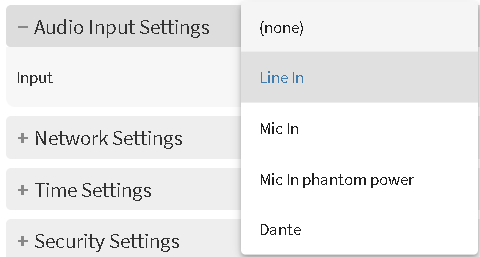
In this section it is possible to select which audio input to consider to feed the SIP Client of the device (for bi-directional audio calls). It is an exclusive selection, only one audio input at a time can be used.
|
Item |
Description |
|---|---|
|
Input |
Allows to select the desired audio input interface among:
Default: “None” - (M400, TPA400, MPA400, MR400) Default: “Line In“ - (MPI400) |
|
Gain (dB) |
Sets the gain of the selected input (only available for mic Phantom and mic in) Default: 0dB |
Network Settings
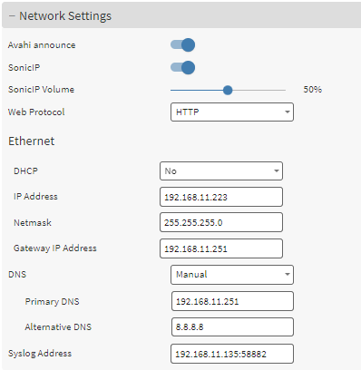
In this area, it is possible to configure the device’s network interface and few other functions.
IP Audio Client, like all other Barix products, supports the Dynamic Host Configuration Protocol (DHCP), which allows the device to acquire an IP address available from a pool of addresses hosted by a DHCP server. It is the server that offers an IP address to the device when discovered on the network. The IP address offered by a DHCP server comes with a lease time, meaning that when the leased time is over the DHCP server re-issues the IP addresses to the devices on the network, with the possibility that it might assign a different address than the one assigned previously. In addition, the DHCP server provides all associated information to the requesting device, such as subnet, gateway, and DNS addresses.
|
Item |
Description |
|---|---|
|
Avahi announce |
This enables/disables the Avahi service, which is the network discovery daemon based on mDNS/DNS-SD used by one IP Audio Client device to discover in the network other IP Audio Client devices. Avahi assigns a default hostname to the IPAC device which can be used to access the device’s web interface, the hostname is unique per each IPAC device and resides on the .local domain: “barix-<MACLast6Digits>.local” (e.g. “barix-091f09”). When enabled the device sends a query packet on the network at the Multicast IP address: 224.0.0.51 on port 5353 as defined by the mDNS protocol. The interval at which these query packets are sent doubles as time passes and no other devices are found in the network. Default: Yes |
|
Sonic IP/Sonic IP volume |
Enable/disable the Sonic IP function so the device announces its IP Address during boot time. Set the volume of the SonicIP with the corresponding slide. Default: Yes |
|
Web protocol |
Configure the protocol used to access the web interface of IP Audio Client. It can be HTTP or HTTPS. When set in HTTPS the communication between the browser and the device is encrypted. The application uses a self-signed certificate for the SSL/TLS authentication, not one from a CA (Certificate Authority) considered safe from web browsers. For this reason when using HTTPS the browser will warn that the certificate used is not a trusted one (NET::ERR_CERT_AUTHORITY_INVALID). To continue and open the web interface it is necessary to advance manually, “forcing” the browser to trust the self signed certificate. The connection and data communication will be fully encrypted. Default: HTTP |
|
DHCP |
Set the DHCP (Yes) or Static IP addressing mode (No). Default: DHCP |
|
DHCP hostname only available in DHCP mode |
Provides the DHCP with an hostname to easily identify the device in the DHCP list of leased IP addresses. Default: " " |
|
Static IP mode
|
IP Address It is the fixed IP address of the RetailPlayer device. The IP address is the unique identifier of a device on a network, in case of static assignment make sure that no other device on the same network has the same IP address assigned to the RetailPlayer |
|
Netmask In addition to the IP address, it is mandatory to provide information about the subnet mask. The subnet mask indicates which bits in the IP address are used for the network portion and which bits for the host portion. It is common in Class C LAN to see 255.255.255.0, this configuration indicates that the first 3 octets of the IP address (e.g. 192.168.1.100) are dedicated to the network identification, while the last octet (e.g. 192.168.1.100) is dedicated to the host identification on the network |
|
|
Gateway IP address The Gateway IP is the address of the device that bridges your Local Area Network with the Internet. Typically is a router where devices on a LAN are connected. For using the RetailPlayer in all its cloud-based features, but also to receive a stream from an internet radio in stand-alone mode, for example, it is essential to provide this address. If you are not sure about the Gateway address in your network contact your network administrator |
|
|
DNS auto |
Automatic Domain Name System resolution. If set in Auto the DHCP server will provide the address of a DNS server to contact for the IP name resolution process. |
|
DNS manual |
If DNS is set to Manual the device expects the Primary and Alternative DNS server fields to be filled with the related information. When Ethernet IP method is set to Static, DNS will always be set Manual and it is mandatory to provide the address information |
|
Primary DNS and Alternative DNS |
This address is for the Domain Name Server. It tells the RetailPlayer which DNS server to contact to resolve domain names into IP addresses. I.e the address of an internet radio like http://barix.streamguys.net/Barix_hi has to be translated into an IP address, this is the job of the DNS server. The alternative DNS is a backup resolution in case the primary DNS server is down. The alternative DNS is not a mandatory field. If you are not sure about the DNS Server address to be used, contact your network administrator. |
|
Syslog Address |
Enables the remote syslog to send system data to a remote server over UDP. Provide a valid <IP_ADDRESS:PORT> to start logging data to the remote server. After enabling remote syslog, the internal logging function is disabled. Default: Disabled (empty) |
Time Settings
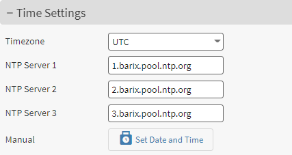
It's important that the IP Audio Client device operates running the correct date and time, especially if a scheduler is configured and the device is not installed in a UTC timezone. IP Audio Client uses an NTP daemon to set its system time. The NTP protocol is used on the standard port 123. The time set by NTP is in UTC, to configure the local time it is necessary to select the correct timezone from the “Timezone” drop down.
On the web interface, the time settings allow the user to change the default NTP pools used by the device. This is because in some situations, customers might be using their internal NTP servers, or they simply prefer to use others. The fields accept either a domain name (which requires a valid connection to the DNS to be able to associate an IP Address to the DN) or an IP Address. It is possible to check the system time in the Status page of the device.
NTP sends packets once every 4mins to the same NTP server to check for clock updates. By leaving the configuration fields empty it is possible to disable the NTP function.
In case an NTP server is not reachable (e.g. device must work offline) IPAC also offers the possibility to set its own time manually. Click on “Set Date and Time” button to enter the information.
When setting the Date and Time manually the configuration is lost after a reboot. For this reason, where possible, always try to adopt NTP to set the time automatically at every boot.
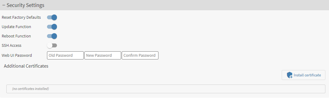
Security Settings
This area is dedicated to secure the login to the device web interface device and to enable or disable the possibility to run critical operations: reboot, reset to factory defaults and update
|
Item |
Description |
|---|---|
|
Reset factory defaults |
Enable or disable the possibility to reset the device to factory default from the web UI Default: Enabled |
|
Update function |
Enable or disable the possibility to update the device from the web UI Default: Enabled |
|
Reboot function |
Enable or disable the reboot function of the device from the web UI Default: Enabled |
|
SSH access |
Enable or disable SSH service. Only enable SSH Access upon request of Barix support, otherwise leave the option disabled. Default: Disabled |
|
Web UI password |
Set the password to access the web interface of the device. If a password is already set another field is displayed: OLD PASSWORD, which is required to modify the current password default username: admin (it cannot be changed) default password: printed on the backside of the device |
|
Additional certificates |
Allows the possibility to upload custom .crt certificates to the device. Useful when the device is used in private enterprise networks where a private CA is in place to validate secure connections Default: None |
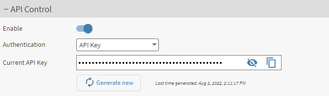
API Control
IPAC devices offers a REST API that can be used to set and retrieve configuration parameters from the device. This enables (i.e.) users the possibility to build personalized web applications, like CMS (Content Management System) to interact remotely with multiple IPAC devices or to integrate IPAC in thrid party solutions able to send API requests over HTTP(s).
Please find at this link the API documentation to start programming your custom web app: IP Audio Client API
The settings available to configure the access to the API are:
|
Item |
Description |
|---|---|
|
Enable |
Enable or disable the API endpoint Default: Enabled |
|
Authentication |
Choose the desired authentication method to be adopted by the API between API Key or None. Refer to the IP Audio Client API documentation to know how to use the API Key Default: API Key |
|
Current API key |
Currently configured API Key. It is possible to copy the key in the clipboard, modify it by clicking on its field or re-generate the key with the corresponding “Generate new” button. The timestamp of the last generated key is available. When a new API Key is generated the previous one becomes invalid. Default: randomly generated API Key |
SUBMIT
By clicking on the button SUBMIT all the changes made in the SETTINGS page are applied in the configuration.
By clicking on CANCEL all the changes are not applied and the fields return to their previous inserted value.
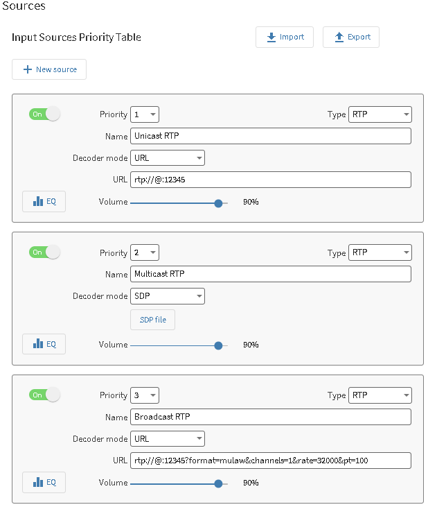
Sources
A source is an originating source of audio, the application allows to arrange sources in 5 priority layers where the layer with the lowest index assigned has more importance compared to the layer with the highest index. Meaning that Layer 1 is the most important and will play on top of any other layer, layer 5 is the least important and will play only in absence of incoming audio in any one of the other layers.
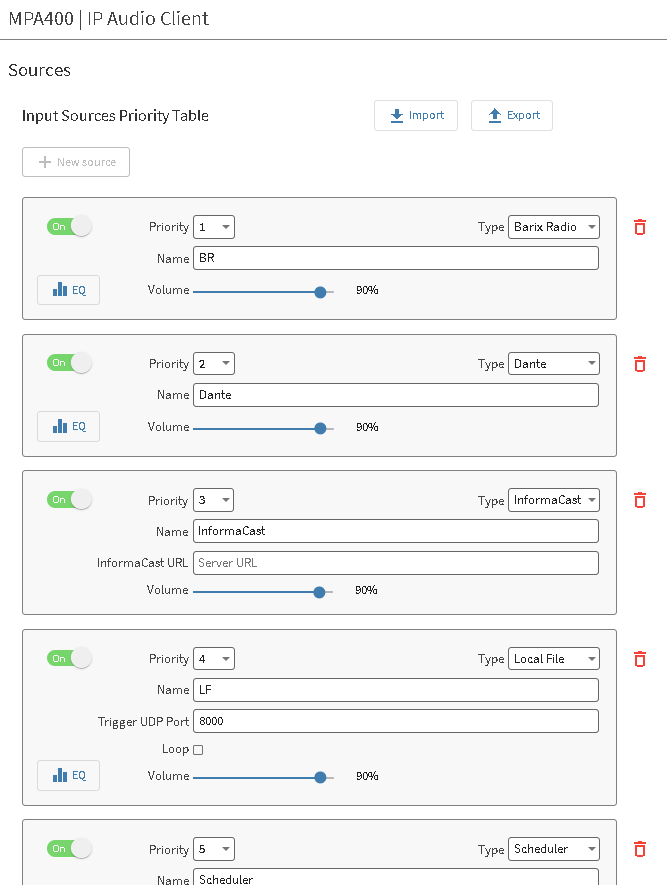
Each layer represents a priority level and a source type can be assigned to it. Use the “New Source” button to add another source in the configuration, the maximum number of sources supported is 5.
Use the BIN icon to remove that source from the configuration.
On the top side of the page there are IMPORT and EXPORT functions used to import / export the current source configuration in JSON format. This can be used to easily replicate the same configuration on multiple IPAC devices or to prepare the configuration to be sent in the API call used to configure all sources.
It is possible to import .json files exported by other IPAC devices running the same firmware version
The common functions available in each layer/source are:
|
ON/OFF |
Allows to switch the corresponding layer on or off |
|
Volume |
Set the volume for the corresponding layer relatively to the master volume configured in the settings page. The change is applied in real time |
|
Name |
Each layer can be assigned a name that is the name of the layer |
Below are all the source types available for each layer/source:
-
InformaCast (only licensed devices)
-
SynApps
-
Dante® (only licensed devices)
-
SIP
-
Paging (IC Paging / Simple Paging)
-
RTP
-
UDP
-
HTTP(s)
-
Local Files
-
USB
-
Scheduler
-
Barix Radio
Default source configuration
1 or 2 sources are ENABLED by default, depending on the IPAC device purchased: SynApps and InformaCast. Where InformaCast is only enabled and available on devices running the Singlewire’s license.
This allows the device to automatically register with the corresponding mass notification servers as soon as they are plugged. Read the following chapters for more information.
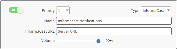
InformaCast
SingleWire's InformaCast is a mass notification platform that streams audio to certified endpoints registered with the InformaCast server. This is how the configuration of an InformaCast source looks like:
InformaCast License
Singlewire's InformaCast requires a license in order to run on IP Audio Client, just like on any other Singlewire certified endpoint. Make sure to order the right PN when purchasing the IPAC device. When your device is running the correct InformaCast license its Feature will appear as "InformaCast" in the System Status → Licenses as per below screen

IPAC implements the InformaCast API that governs how the IPAC device:
-
Registers with the InformaCast server
-
Receives commands and notifications
For this reason the configuration is easy and straightforward.
InformaCast registration
The registration process with an InformaCast server doesn't require any configuration if the server is reachable from the network where the device sits. IP Audio Client devices implement registration over SLP (Service Location Protocol), if that fails TFTP (Trivial File Transfer Protocol) is used (requires DHCP option 150 to be configured in the DHCP). If none of the mentioned protocols are available in the network or failing it is possible to specify manually the URL in the "InformaCast URL" field in the Source configuration.
The automatic registration process is well described in the below logic diagram (picture taken from InformaCast IP Speaker registration notes):
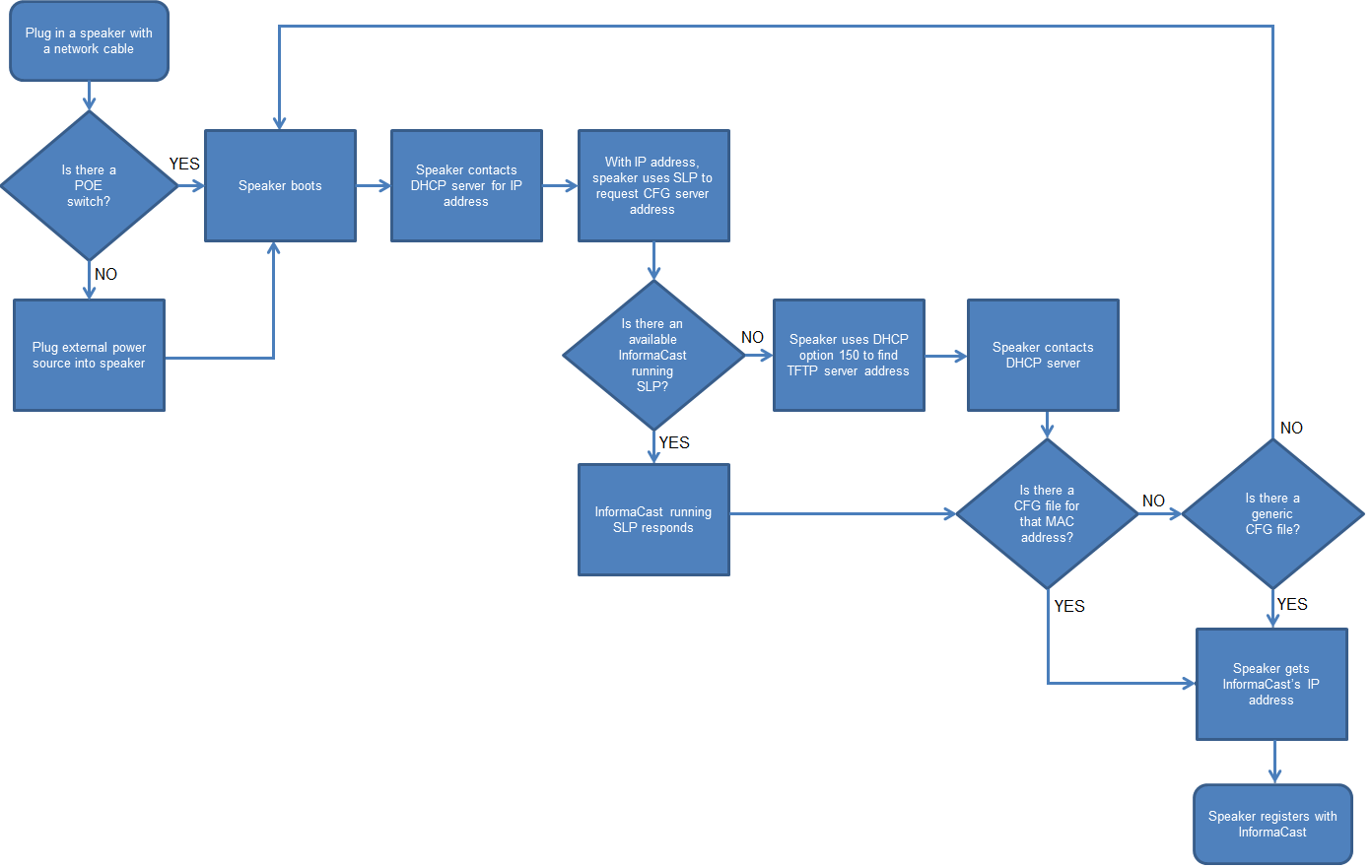
For more information and troubleshooting steps about the InformaCast registration visit this link provided by SingleWire: IP-Speaker-Registration-and-Troubleshooting-Guide
In case your InformaCast server and the IPAC device is behind a firewall, check this link: Informacast Inbound / Outbound connections
InformaCast Manual registration
When entering the URL manually in the source configuration of IP Audio Client the URL should be: http://<ICast_server_IP>:8081/InformaCast/admin
After the registration the device heartbeats the server once every 5 minutes to keep the server updated about its existence. This interval value cannot be configured by InformaCast (despite there is a function on InformaCast that allows it), it is fixed in the configuration file of the device. If the device doesn't send the heartbeat to the server the server will consider the device "expired" and it is not possible to send notifications to it.
InformaCast IDLE Audio
IDLE Audio is a function within the InformaCast source available only when the InformaCast URL is explicitly specified (the IDLE Audio configuration fields appear when the user starts typing in the InformaCast URL field).
This function allows to specify an RTP stream to play as background music when no notifications are sent. It can be seen as a "source-in-a-source". Of course it plays in the same priority level of the InformaCast source (but not over InformaCast notifications), thus if Background music is playing on Priority 1, lower level priority sources will never play.
The url RTP scheme should be as follow: rtp://<IP_Address>:[Port]
It can be a unicast or multicast IP Address:
-
Unicast example: rtp://0.0.0.0:12345 (the rtp://@:12345 schema is not supported for InformaCast Idle audio)
-
Multicast example: rtp://239.0.0.1:12345
IDLE Audio format specifies the decoding format to be used for IDLE audio. Available formats are
-
PCM @ 44.1kHz 16bits mono
-
G711 uLaw 8kHz mono
How to setup InformaCast on IP Audio Client and receive notifications
|
1 |
Make sure that your InformaCast Server is running and that a network communication with the IPAC endpoint can be established. By default IPAC licensed devices will boot with InformaCast already enabled in the Priority source 1. The highest priority source. Boot your IPAC device. IPAC devices will try to automatically register with the InformaCast server using SLP (Service Location Protocol), if this fails it will try with TFTP (DHCP Option 150 configured and available in the DHCP of the network), if this fails the device will not be able to register automatically with the server, thus it will be necessary to enter the URL of the InformaCast server manually in the source configuration. The speaker status will confirm the success of the registration when the device is registered with the ICast server providing the time of the last successful registration process. 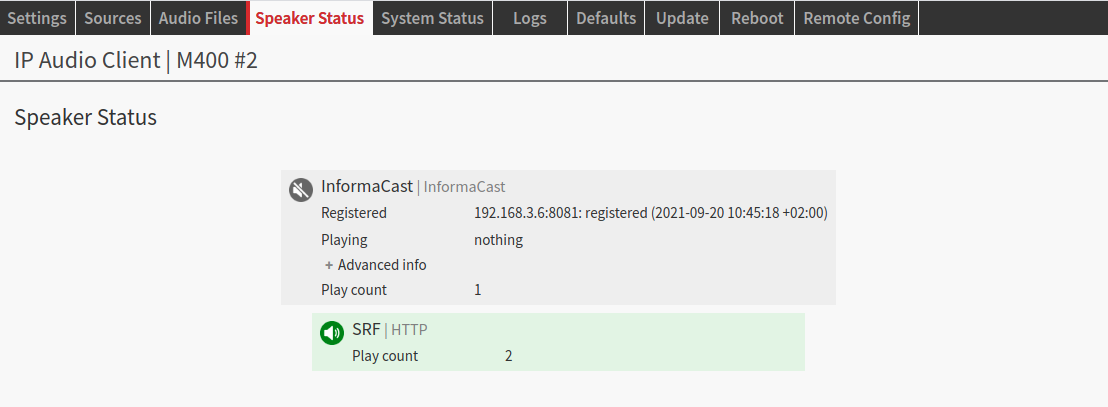
|
|
2 |
Navigate to the InformaCast dashboard typing the URL of your server in the browser (typically the administration dashboard can be reached at: https://<ICast_IP>:8444/InformaCast/admin). In the dashboard it is possible to check the number of speakers currently registered with the server and ready to receive notifications. 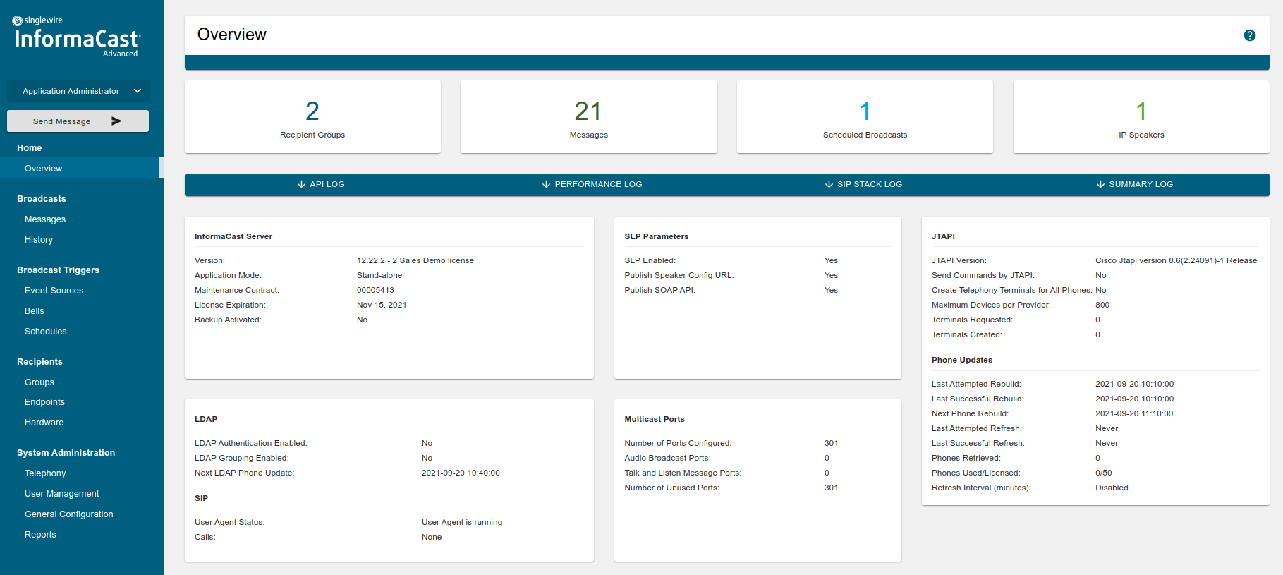
|
|
3 |
Clicking on the IP Speakers icon in the top right corner of the dashboard opens the list of IP Speakers with all the details. Underneath the IP speaker list, there is an important flag "Automatically Add Hardware IP Speakers", if this option is not flagged IP Speakers will not be listed automatically, but have to be entered manually following the IP Speaker creation procedure (refer to InformaCast user guide) 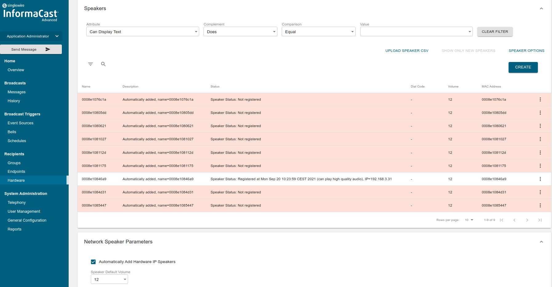
|
|
4 |
Create a recipients group in Groups → Recipient groups accessed from the left side bar menu. Follow the on screen instructions to add IPAC devices to the group and confirm the group creation. This step is not mandatory as you can also send notifications to a pre-defined group called “all recipients” but it’s useful if you want to test only one IP Speaker or a group of IP Speakers. 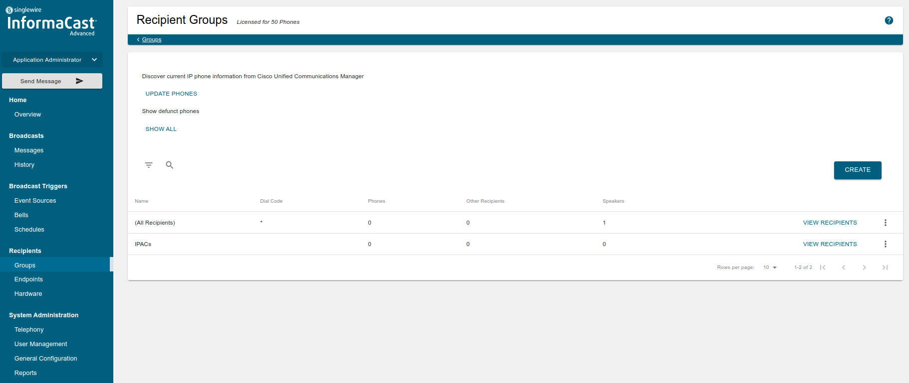
|
|
5 |
Test an audio notification: click on "Send Message" in the left side bar, select a "Pre-Recorded" audio notification type, select the recipient group that has to receive the notification and click on SEND 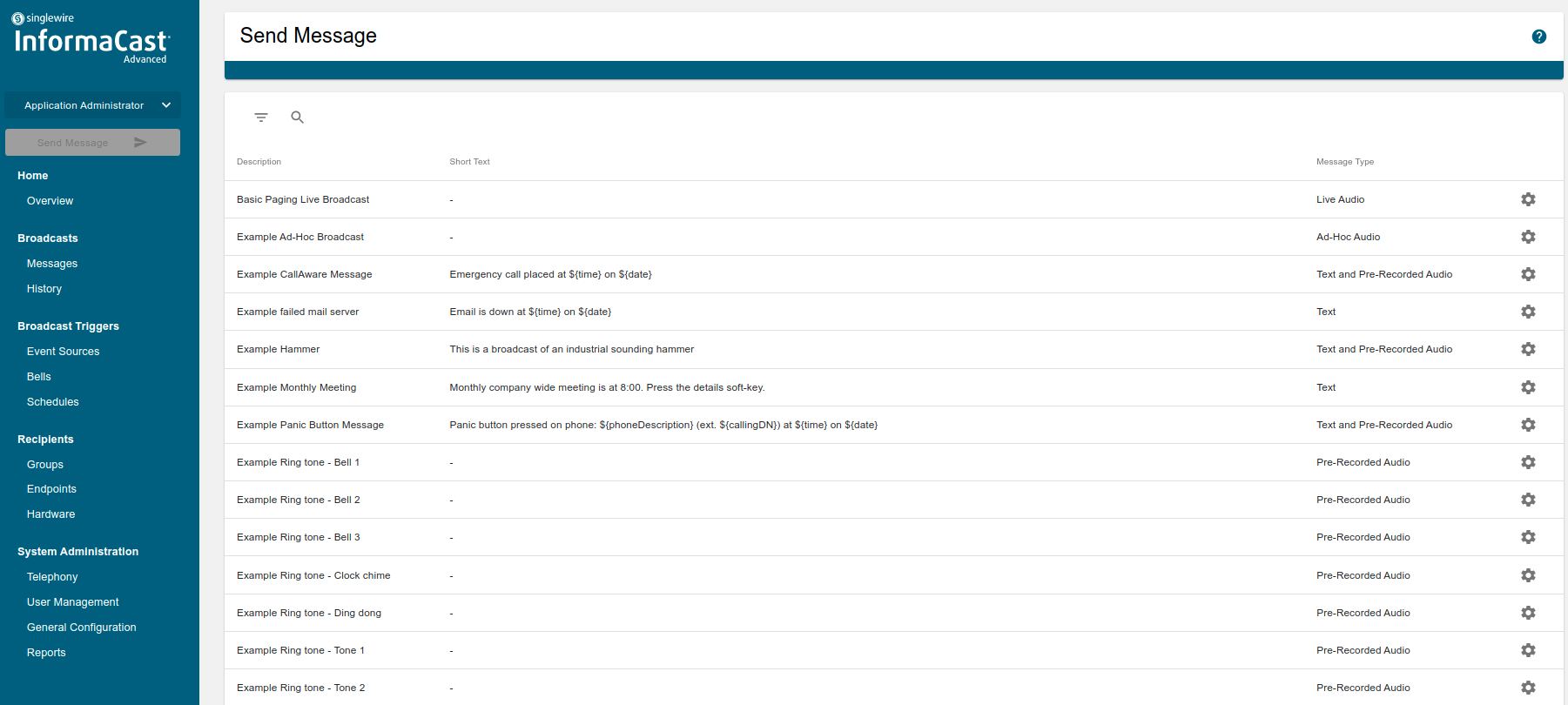
|
|
6 |
While the notification is received on IPAC device it is possible to monitor the status in real-time. Check the “Advanced” tab to view more details such as the Multicast address used by InformaCast to broadcast the notification (this address is configurable in the InformaCast server) 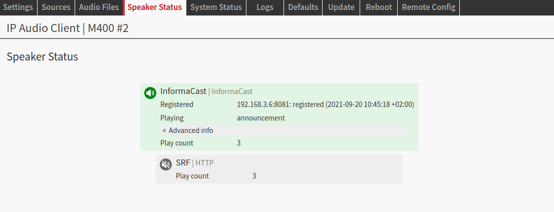
|
SynApps
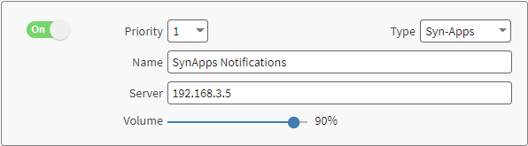
SynApps Revolution by Intrado is a mass notification platform that streams audio to certified endpoints registered with the SynApps Revolution server. This is how the configuration of a SynApps source looks like on the IPAC device:
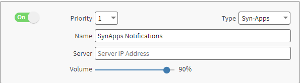
IPAC implements the SynApps API to: register with the SA server, receive commands and notifications. For this reason the configuration is easy and straightforward. SynApps is switched ON by default at priority 1 on any new IPAC device. If the device is licensed for InformaCast as well, it is ON by default but in the priority layer 2.
SynApps registration
The registration process with a SA server from an IPAC can be automatic or manual.
Automatic registration requires the DHCP server in the network to have enabled and configured DHCP Opt 72 (more information on DHCP options here). Below is an example of a router where it is possible to specify the DHCP option and associate the IP Address of the SA server to it.
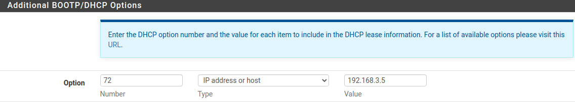
Once this is configured the DHCP will release this information to the IPAC device when it will try to find in the network the service provided by the SA server during boot time. If your device was already powered when the DHCP option was configured, reboot it to make sure it will find the information it needs to connect automatically with the SA server.
On IPAC devices the automatic registration is the default option. Leave the “Server” IP Address field empty in the source configuration to benefit from the automatic registration process.
Manual registration is an option to use when for example DHCP Opt 72 is not available in the DHCP server present in the network. Manual registration means that the IP Address of the SA Server IP address has to be manually entered in the SynApps source configuration in the IPAC device. See below example:
After the first registration the device heartbeats the server once every minute to keep the server updated about its existence. This interval value cannot be configured on the device nor on SA Server, it is fixed in the configuration file of the device. If the device doesn't send the heartbeat to the server the server will consider the device "expired" and it is not possible to send notifications to it.
How to setup SynApps on IP Audio Client and receive notifications
|
1 |
Make sure that your SA Server is running and that a network communication with the IPAC endpoint can be established. By default IPAC devices will boot with SynApps already enabled in the Priority source 1 (Priority source 2 if InformaCast is also running). If, after boot, the connection with the server can be established and the DHCP Server in the network provides DHCP Opt 72 the device will register automatically, if this fails or if DHCP Opt 72 is not configured or available the device will not be able to register automatically with the server, thus it will be necessary to enter the URL manually in the source configuration. Here is an example of what is shown in the speaker status after the device successfully registered with a SA server. 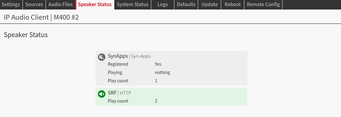
|
|
2 |
Navigate to the SynApps dashboard typing the IP Address of your server in the browser (typically the administration dashboard can be reached at: http://<SA_IP> 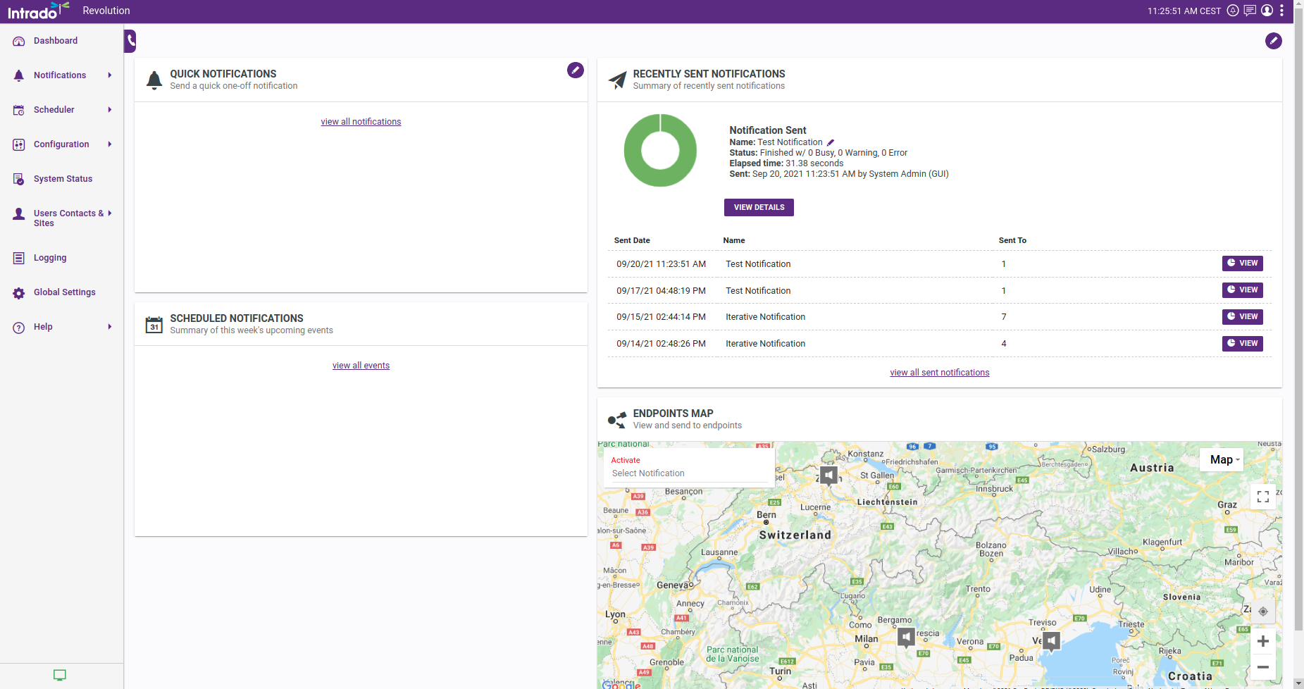
|
|
3 |
Navigate in the Configuration → IP Devices - Here is where all the active / inactive IP Devices appear, including IPAC devices. By clicking on the settings icon on a specific device it is possible to edit its details, i.e. assigning a name. 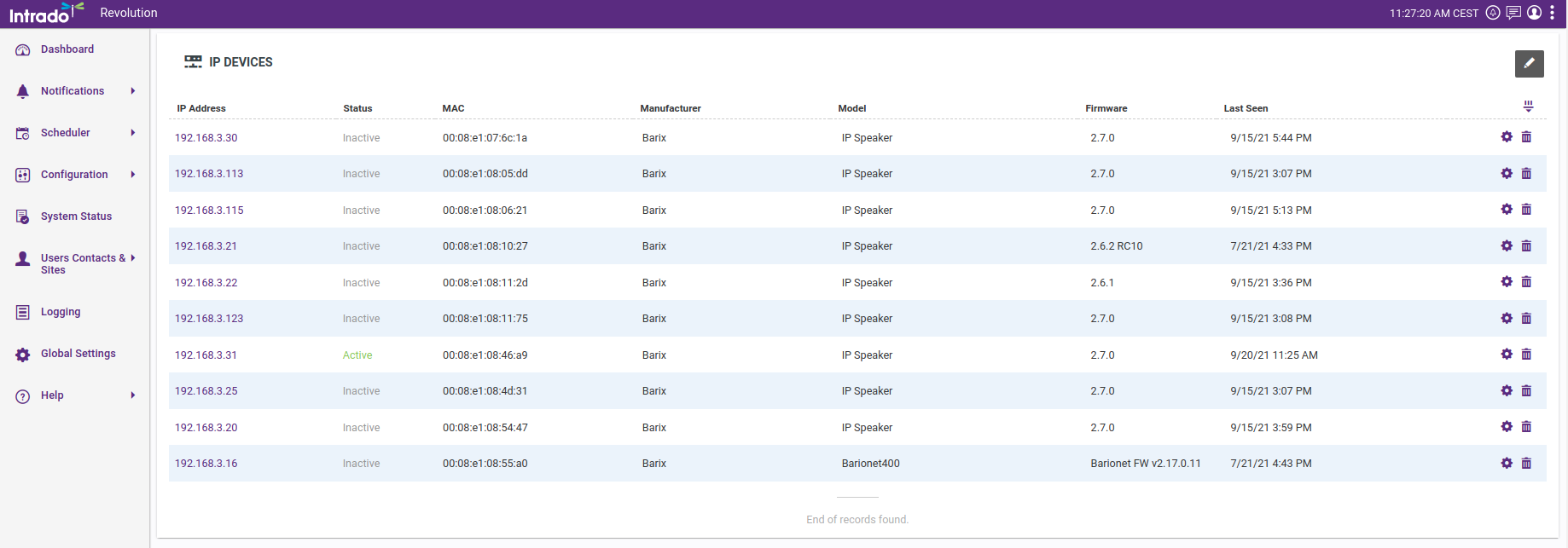
|
|
4 |
IPAC Devices are registered as Endpoints in the SA platform, devices capable of receiving audio notifications. Navigate in Configuration → Endpoints. All endpoints available and ready to receive notifications are listed. If it's the first time the device registers with the SA Server it might take some time to appear in the endpoint list. In some cases the time could be up to 10-12 minutes. 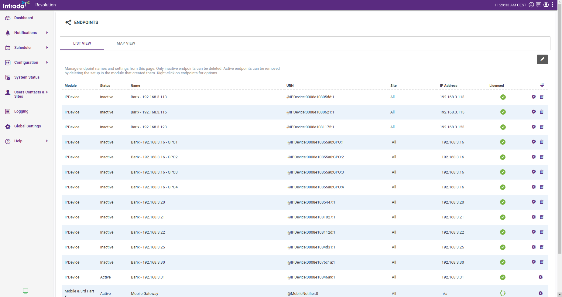
|
|
5 |
Prepare a notification: Locate Notifications → Manage → New Notification 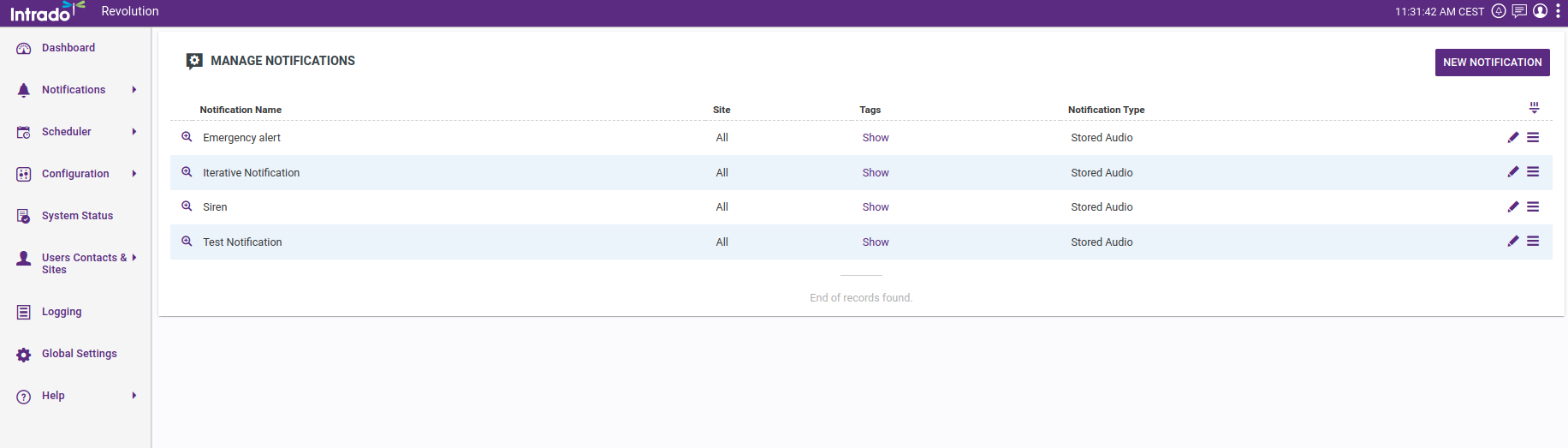
Under General → Notification Type select "Stored Audio" 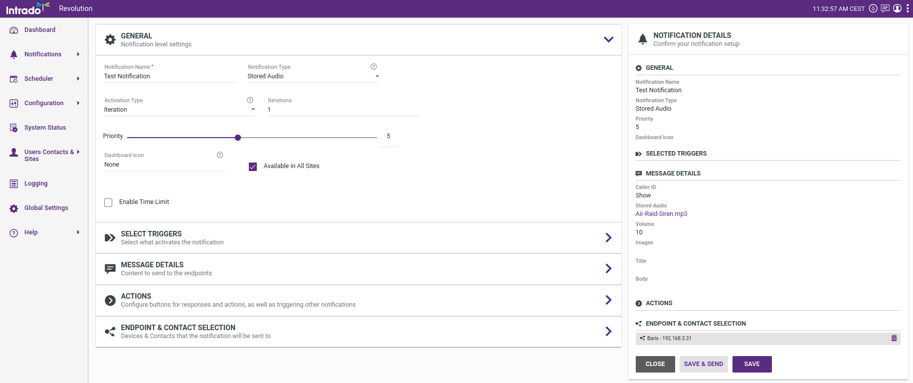
Under Message Details → Select audio: pick an audio file from the ones available. i.e "Air-raid-siren.mp3" 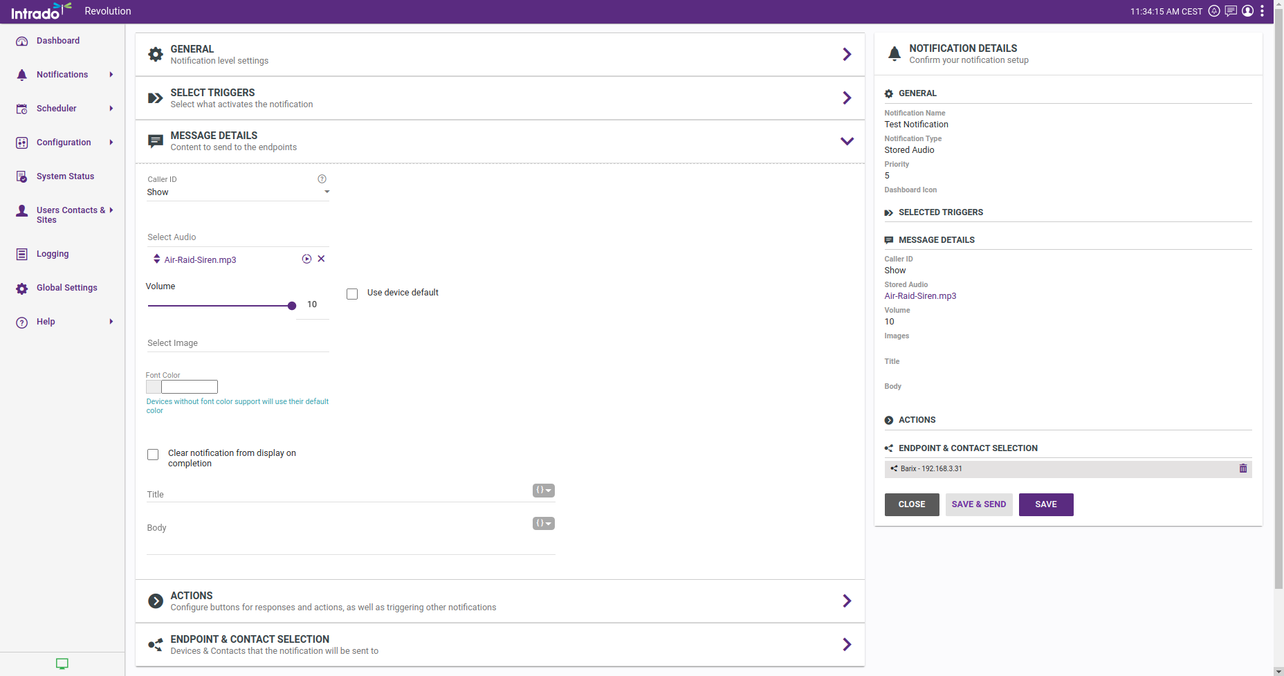
Under Endpoint and Contact Selection select the IPAC devices that need to receive the notification 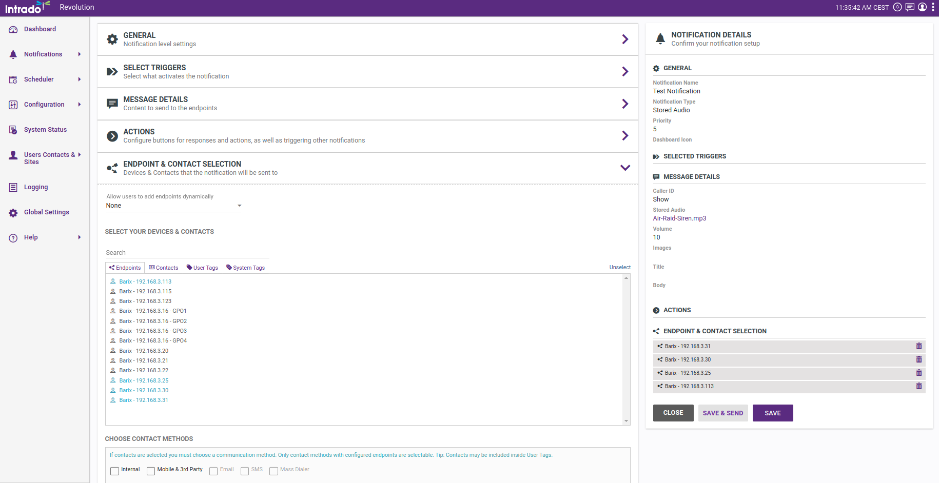
Now you can SAVE or SAVE & SEND. Clicking SAVE & SEND will send the notification to the selected endpoints |
|
6 |
Monitor the notification receipt in the Speaker Status of the IPAC device while it is playing. The status will show the RTP Mutlicast address used by SynApps platform (this address is configurable in the SynApps server) 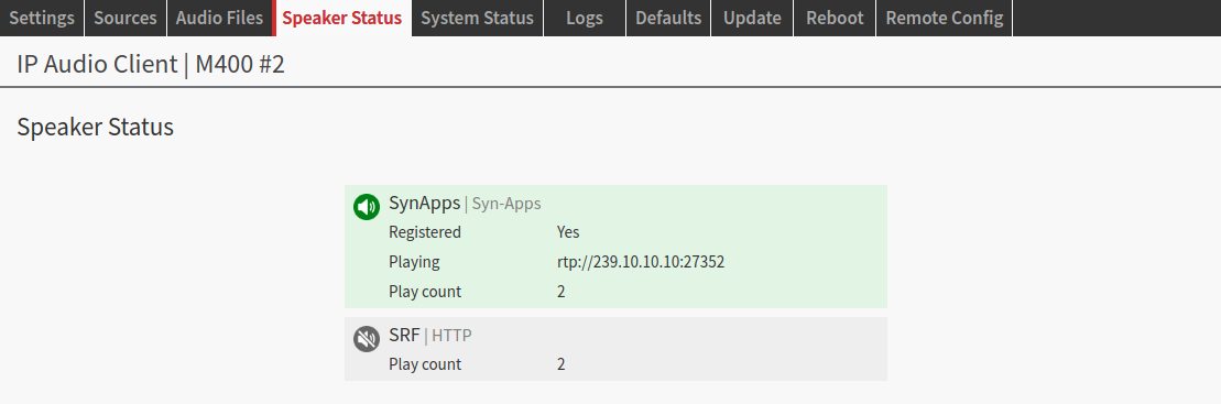
|
For more information on SynApps requirements for firewall configuration visit Intrado SynApps official user manual: https://www.syn-apps.com/downloads/User%20Guides/Revolution_Help/en-us/Content/Installation/System_Requirements.htm
Paging
IPAC devices support 2 paging modes:
-
IC Paging
-
Simple Paging
Both paging solutions are made by Barix and allow any IPAC device to receive audio from any one of the below Paging Master stations:
|
Paging Master |
Paging Mode |
|---|---|
|
Paging Gateway M400 |
IC Paging |
|
Annuncicom PS Touch |
IC Paging / Simple Paging |
|
Annuncicom PS1 |
IC Paging / Simple Paging |
|
Annuncicom 100 |
IC Paging |
|
Annuncicom 200 |
IC Paging |
|
Simple Paging iOS / Android app |
Simple Paging (requires an Exstreamer 100 to be configured as a Gateway in the system) |
|
IC Graph |
IC Paging |
IC Paging
IC Paging is the Barix Paging solution that works relying on the Barix Paging Protocol, abbreviated BARP. Barix developed a proprietary protocol to allow "BARP devices" to communicate between each other providing audio, control and status messages over a Broadcast or Multicast addresses. An IC Paging system includes:
-
one or more Master station(s) or ICMASTER running IC Paging firmware
-
one or more Endpoint(s) or ICCLIENT running IC Paging firmware
-
one or more Endpoint(s) running IPAC
Firmware Note
IC Paging firmware running on Annuncicom or Exstreamer 1xx / 2xx devices is not the same as the one running on IPAC devices. IP Audio Client is a self-contained firmware that implements compatibility with IC Paging devices, it is not an IC Paging firmware like the one deployed on legacy Annuncicom or Exstreamer 1xx / 2xx devices
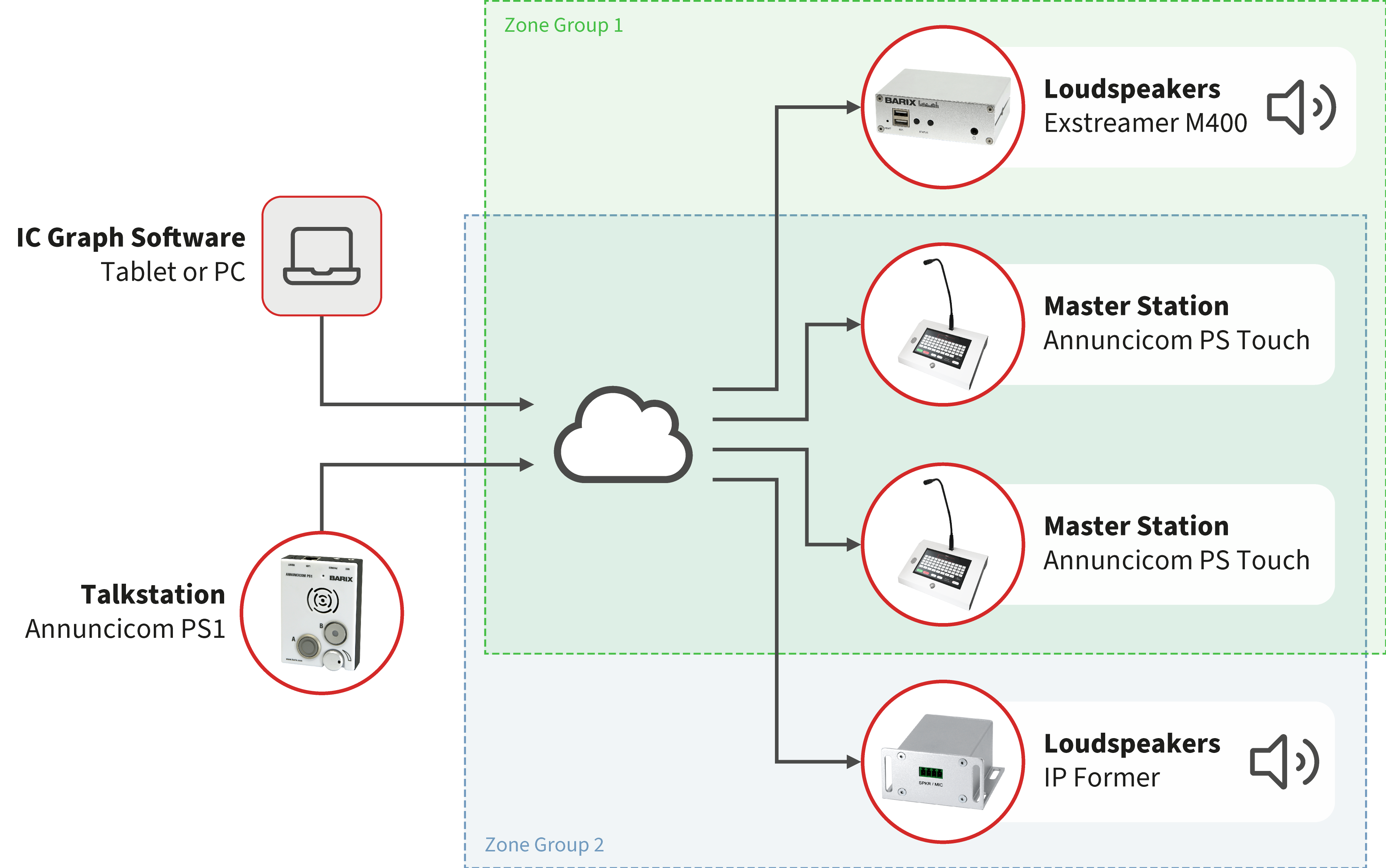
IC Paging implementation on IPAC devices allow IPAC to become endpoints, devices able to receive a stream coming from a master station. A typical example and use case is running the IC Paging firmware on an Annuncicom PS Touch or PS1 or any other Annuncicom device supporting IC Paging firmware and configure multiple endpoints to be part of different zones, so that it is possible from a button on a master station (correct name: PTT or Push-To-Talk) to page in the desired endpoints while pressing the button.
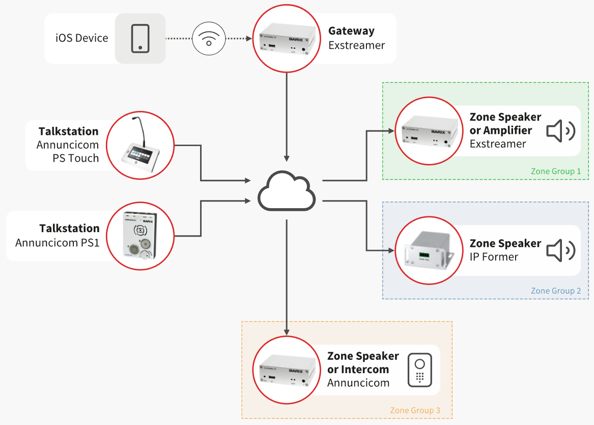
Below is a diagram showing the configuration of an IC Paging based solution:
IC Paging Source Configuration:
The default configuration of IC Paging when first enabled matches the default configuration of an IC Paging Master device. If nothing is touched the IPAC device would be able to receive streams from the master immediately after submitting the configuration to enable IC Paging
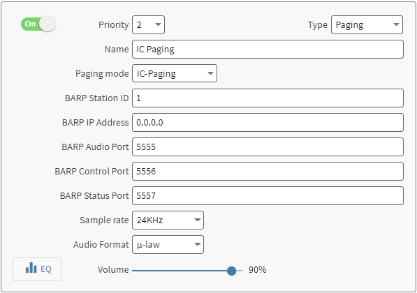
|
Item |
Description |
|---|---|
|
Name |
Modify the name of the priority layer |
|
Paging Mode |
Select between IC Paging / Simple Paging (it is not possible to use the 2 modes in different sources, one excludes the other) |
|
BARP Station ID |
Unique identifier of the paging endpoint (also called Zone ID in an IC Paging system). Different endpoints can be assigned the same Station ID. In the IC Master device is possible to assign every ID to GROUPS to page different groups of IDs using different calling buttons (number of buttons depends on the capabilities of the IC Master device) Default: empty |
|
BARP IP Address |
IP Address used by the endpoint to listen/send on the BARP ports. Modify the BARP IP address to use multicast if communication across different networks is desired, or if your LAN policy is not allowing broadcast. This field cannot be Unicast. The BARP address used by the endpoints should match the one set on the Master station and vice versa. Default: 0.0.0.0 (which corresponds to the broadcast address of the network where the device is installed) |
|
BARP Audio Port |
Endpoint local port used to listen for incoming audio from the master. It is possible to configure any unused port between 5555-5999 Default: 5555 |
|
BARP Control Port |
Endpoint local port used to listen for incoming control messages from the master. It is possible to configure any unused port between 5555-5999 Default: 5556 |
|
BARP Status Port |
Destination port number to send status messages to the master. It is possible to configure any unused port between 5555-5999. Default: 5557 |
|
Sample Rate |
Configure the sample rate according to the selection applied in the Paging Master station. It offers: 8kHz or 24kHz Default: 8kHz |
|
Audio Format |
Configure the audio format according to the selection applied in the Paging Master station. It offers: uLaw or aLaw Default: uLaw |
How to setup IC Paging system
|
1 |
After switching IC Paging Source ON fill in the Station ID field with the desired number. The Station ID is the Zone Group ID used in the BARP protocol to identify one or more endpoint devices. In this example ID 1 is used, all other IC Paging parameters remain with default settings (meaning that BARP will use the Broadcast IP of the network where the device is installed to propagate audio, control and status messages). Click on SUBMIT
|
|
2 |
On the IC Paging master station (a PS1 device in this example) navigate to Configuration → Basic Settings 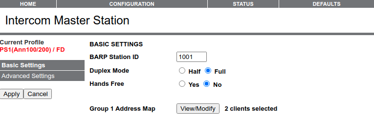
On Annuncicom PS1 only one button / group can be configured, thus only Group 1 Address Map is shown. On a PS Touch or Legacy PS16 Annuncicom this would be from 1 to 8. By default each group contains 10 station IDs or zones. So by default our IPAC endpoint will end up being part of Group 1, since its station ID is set to be “1”. Up to 128 station IDs can be selected to be part of a group. To double check which Station IDs are called from a specific group click on View/Modify related to the group required, the below station selection window appears. It is possible to add/remove IDs from the group. 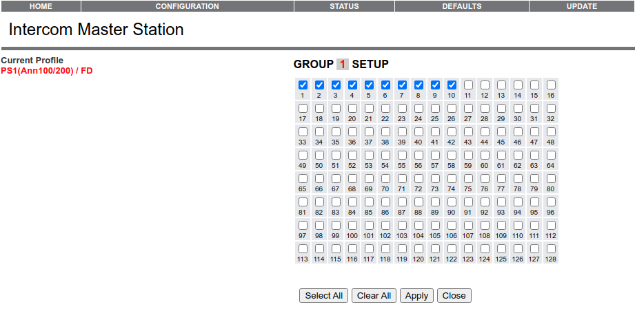
There are no steps required to perform as by default the correct station ID is part of the Zone Group 1. So when pressing the PTT button 1 on the PS1 the IPAC endpoint is called and automatically plays the audio received by the master station, typically from its microphone input. |
|
3 |
Check the BARP settings on the IC Paging Master station. They can be found under “Configuration → Advanced Settings → BARP Control”. The Station ID of Master stations can be any number as far as it is not one already taken by another device in the system. It is used to notify endpoints about which master is sending the audio and control messages in a multi-master environment. The BARP broadcast address is the BARP IP Address to be used by master stations and endpoints. It has to match on both configurations. When it’s 0.0.0.0 means that the Broadcast IP address of the network will be used to propagate audio and control messages and from the master to fetch the status of the endpoints. Multicast can also be used. Unicast is NOT supposed to be used for the purpose of the application. 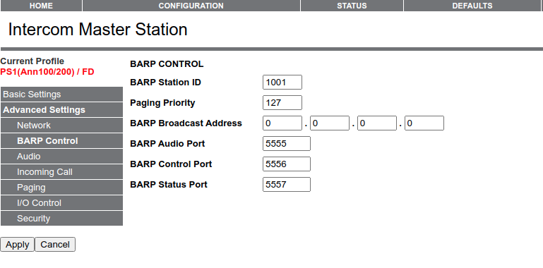
For our example there is no need to change this configuration as it is correct by default. |
|
4 |
Important is to double check the audio format selected in the IC Paging Master. It can be found on the IC Paging Master station under “Configuration → Advanced Settings → Audio” . This is also the default setting on an IC Paging Master device. 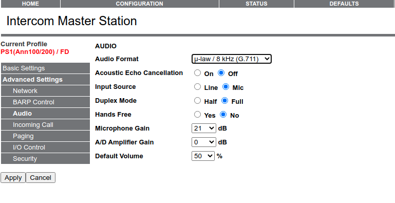
|
|
5 |
The IPAC endpoint is now ready to receive audio from a master station. To summarize, using a DEFAULT configuration on a master station and on an IPAC device, it is only necessary to configure the STATION ID on the IPAC device to be any number from 1 to 10, since the configuration is already applied on IC Paging Master station to page Station ID from 1 to 10 pressing the first button (in case of PS1 device it corresponds to Button “B”) using BARP address 0.0.0.0 and ports 5555 for audio, 5556 for control, 5557 for status, which are the same on all the devices when using the default configuration. When the IPAC device receives audio the Speaker Status changes as follow: 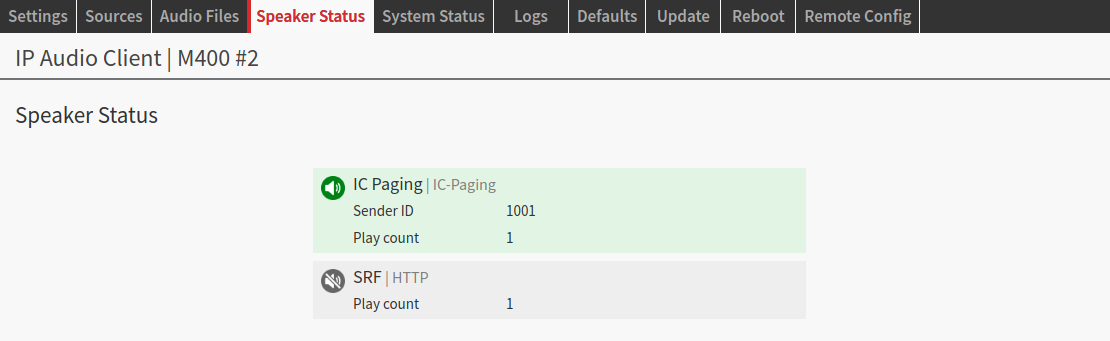
|
IC Paging Network requirements
IC Paging, by default configuration, uses the network’s broadcast address to:
-
Discover other IC Paging devices
-
Send control commands (e.g. start / stop page)
-
Send status information (e.g. zone busy)
-
Audio transport over RAW UDP
In case the broadcast address of the netwokr cannot be used, it is possible to configure IC Paging with multicast. Make sure the network equipment within the subnet where the solution is deployed supports IGMP (Internet Group Management Protocol) for multicast to work efficently.
The ports used are specified in the configuration and can be adapted according to the installation and networking needs. The default ones are:
-
Port 5555 used for the audio transport
-
Port 5556 used for control messages
-
Port 5557 used for status messages
In a multi-master setup, make sure to use different ports for each IC Master.
Simple Paging
Simple Paging is a simplified version of IC Paging, always relying on the Barix Paging Protocol, abbreviated BARP, the Barix proprietary protocol to allow "BARP devices" to communicate between each other providing audio, control and status messages over a Broadcast or Multicast addresses. A Simple Paging system includes:
-
one or more Master station(s) or master devices running Simple Paging firmware
-
one or more Endpoint(s) running Simple Paging firmware
-
one or more Endpoint(s) running IPAC
Firmware Note
Simple Paging firmware running on Annuncicom or Exstreamer 1xx / 2xx devices is not the same as the one running on IPAC devices. IP Audio Client is a self-contained firmware that implements compatibility with Simple Paging devices, it is not a Simpe Paging firmware like the one deployed on legacy Annuncicom or Exstreamer 1xx / 2xx devices
Simple Paging implementation on IPAC devices allow IPAC to become Simple Paging endpoints, devices able to receive a stream coming from a master station. A typical example and use case is running the Simple Paging firmware on an Annuncicom PS Touch or PS1 and configure multiple endpoints to be part of different zones, so that it is possible from a PTT button on a master station to page in the desired endpoints while pressing the button.
Unlike IC Paging, Simple Paging is easier to configure. It just requires the device to be connected and a page can be immediately established. If “zoning” is required, then it is necessary to modify one field only to assign the devices to their relative groups.
Below is a diagram showing the configuration of an IC Paging based solution:
Note that compared to IC Paging, Simple Paging also support the possibility to page from an app installed on Android or iOS devices. This requires the presence of a Simple Paging Gateway device in the system running on an Exstreamer 100.
The setup of a Simple Paging source is straight forward:
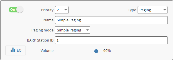
There are not parameters beside the BARP Station ID, which is the Zone ID where the endpoint is assigned to receive a page. On the master device it is possible to assign groups of multiple Zone IDs to PTT to perform calls.
Simple Paging Network requirements
A Simple Paging system runs over an IP Network with the followings architecture:
-
A single segment Local Area Network
-
All nodes on the system has to be on same subnet
-
Smart devices has to be part of same subnet of the same local area network
Simple Paging, by default configuration, uses the network’s broadcast address to:
-
Discover other Simple Paging devices
-
Send control commands (e.g. start / stop page)
-
Send status information (e.g. zone busy)
While the audio transport relies on a randomly picked multicast address. Make sure the network equipment within the subnet where the solution is deployed supports IGMP (Internet Group Management Protocol) for multicast to work efficiently.
The ports used are:
-
Port 5555 used for the audio transport
-
Port 5556 used for control messages
-
Port 5557 used for status messages
Simple Paging System Limits
-
Maximum 128 end-points in one system
-
Maximum 10 masters in one system
-
Maximum 1 gateway in one system
-
Maximum 5 iPhone/Android Paging Application can page simultaneously deploying the Simple Paging Gateway device (not to be confused with the Paging Gateway M400, which works only with IC Paging)
-
Maximum 14 groups can be created on Annuncicom PS Touch
-
Maximum 2 groups can be created on Annuncicom PS1
SIP
SIP stands for Sessions Initiation Protocol and it is the most used protocol for Unified Communication Systems or VoIP (Voice over IP) solutions. One (not more than one) of the priority layers of any IPAC device can be configured to turn the device into a SIP client via the SIP source and benefit from the broad compatibility with many third party vendors to integrate IPAC devices in infrastructures that are already using SIP as their main communication backbone.
A SIP source on IPAC supports 3 operational modes:
-
SIP Server Mode
-
SIP Peer to Peer Mode
-
Both modes combined
SIP Server Mode
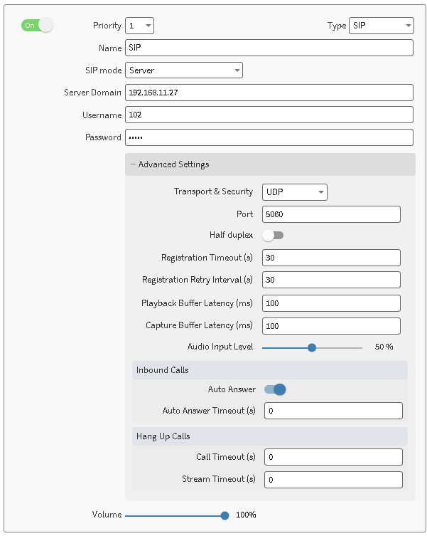
In Server mode the IPAC device allows to enter the values required to register with a SIP server that is used to route and handle the connections and calls between the SIP endpoints. IPAC devices support SIP and SIPS (Secure SIP) protocols (TLS + SRTP) When switching in Server mode the SIP source displays the following options:
|
Item |
Description |
|---|---|
|
Server Domain |
The server url or IP Address that the IPAC device has to register with. It can be the server hostname or the IP Address Default: “empty” |
|
User Name |
The user name for this IPAC endpoint. It is normally the extension number that must be called to reach this extension Default: “empty” |
|
Password |
The password for the user name entered and that has to be used to authenticate the registration of the user name with the SIP Server. When it is optional leave this field empty Default: “empty” |
|
Advanced Settings |
|
|
Transport & Security |
Allows to configure the transport and security protocols to be used to establish the connection and transport data:
Default: UDP |
|
Port |
Allows to configure the SIP negotiation Port Default: 5060 |
|
Half Duplex* |
Enable or disable the half-duplex functionality which allows the device to only "talk" or "listen" and not both at the same time.
|
|
Registration Timeout |
Configure the interval used for the registration with the SIP Server, in seconds.
Default: 30 |
|
Registration retry interval |
Configure the registration retry interval in case of registration failure, in seconds. Set to 0 to disable auto re-registration.
Default: 30 |
|
Playback Buffer (ms) |
Sets the desired target buffer for the SIP playback interface. An higher value increases the overall delay gaining on quality, a lower value decreases the delay but the quality of the play-out might be affected by drops or errors. Default: 100 |
|
Capture Buffer (ms)* |
Sets the desired target buffer for the SIP capture interface. An higher value increases the overall delay gaining on quality, a lower value decreases the delay but the quality of the play-out might be affected by drops or errors. Default: 100 |
|
Audio Input Level* |
Fine tunes the audio input level to increase or reduce the input level into the SIP call. Default: 50% |
|
Auto Answer* |
Enables or disables the posibility to auto answer an incoming call. When auto answer is disabled it is only possible to pick up calls when a Digital Input is closed. Default: enabled |
|
Audo Answer Timeout* |
It sets a timeout to automatically pick up an incoming call. Only used when Auto Answer is enabled. |
|
Call Timeout |
Configure the maximum duration of an established call, in seconds. Set to 0 to disable. Default: 0 |
|
Stream Timeout |
Configure the timeout that the SIP client should wait to close the current call in the case it does not detect audio from the remote party. Set to 0 to disable. Default: 0 |
*: Parameter only available on IPAC devices supporting bidirectional SIP communication.
SIP Server Response Codes
When in Server mode the Speaker status provide useful feedback on the server replies when the device attempts to register with it, below is an example of successful registration
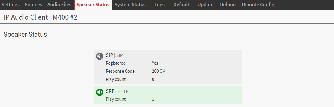
More information on SIP Response codes here - Those codes are used to inform the user about connection status between the endpoint and the server.
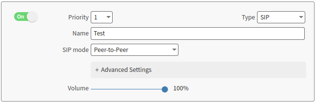
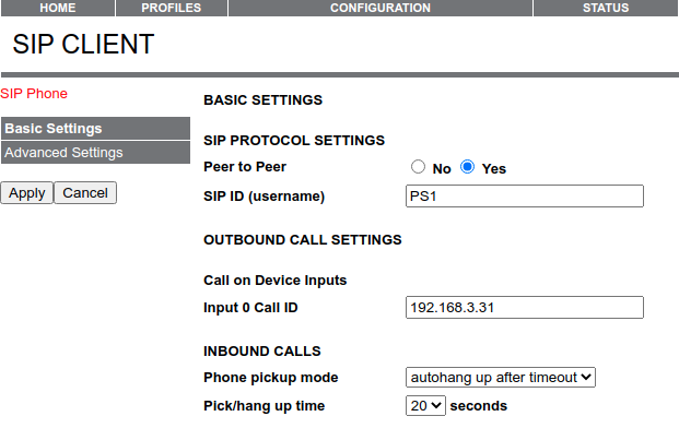
SIP peer-to-peer Mode
It is the most simple SIP mode, which doesn’t require a server for the nature of its working principle. A peer-to-peer communication is a connection established between 2 endpoints only (the latency in this mode is approximately 147 ms, using an Annuncicom 100 as encoder). When in peer-to-peer mode the IPAC device can be called (it is working as a SIP receiver) by any other SIP capable device, the entire connection establishment, setup and dismounting is performed using SIP standards. Below a representation of a source configured in SIP peer-to-peer mode:
To call an IPAC device in P2P mode it is enough to:
|
1 |
Switch ON one source to be SIP in peer-to-peer mode and click SUBMIT 
|
|
2 |
When pressing the button “A” on the PS1 the call is started to the IP Address of the IPAC device. Pressing the button again terminates the call. |
|
3 |
During the call the speaker status changes indicating the caller details 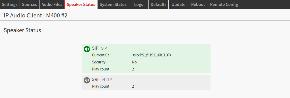
|
RTP
This source type allows the device to receive an audio stream using the Real-Time Transport Protocol. RTP Playback allows any IP based audio device that is able to stream over RTP to feed audio to IPAC devices. Examples are:
-
BGM Distribution where a Barix Instreamer feeds one or more IPAC device(s) streaming audio to an RTP multicast address (instead of an Instreamer it is possible to use also VLC or FFMPEG to stream audio over RTP)
-
Audio Distribution where a Barix Multicoder feeds one or more IPAC device(s) streaming audio to an RTP multicast address
-
Annuncicom PS1 running an Any to All or IP Intercom firmware streaming voice announcements to one or more IPAC devices
-
Barionet devices running FFmpeg to stream RTP every time a contact is closed (i.e. to stream an alarm, a pre-recorded message triggered by a switch or a panic button…)
|
Item |
Description |
|---|---|
|
Decoder mode |
|
|
URL |
The RTP Address where the device has to connect to in order to receive the audio stream. It supports multicast or unicast addresses. Multicast URL scheme: Unicast URL scheme:
where any one of the following values can be assigned to the fields above:
Example: play a G711 uLaw 32kHz Mono stream generated by an Instreamer Classic (payload type = 100) use the following URL scheme:
When the manual format setting is used it overrides the automatic format detection. HINT: use an application like Wireshark to identify the data format being transmitted by the sending device Default: “empty” |
|
SDP |
Uploading an SDP file offers an easy way to setup the decoder to play RTP streams, especially the ones that do not use a standard payload type. When uploading an SDP file ensure that the mandatory attributes are provided. Below is an example of SDP file from a Barix Multicoder M400 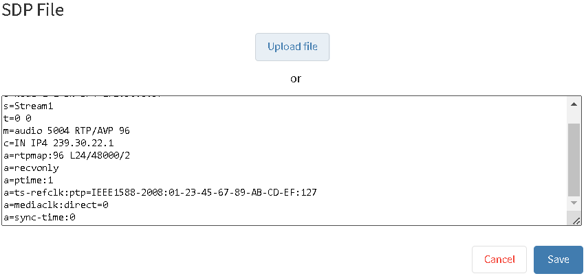
Default: “empty” |
Synchronized Play-out and Delay
The RTP source in IPAC offers a reliable way to play audio synchronized among different devices part of the same installation, with an end to end delay of approx. 190ms when decoding a PCM stream (with MP3 ithe delay is around 240ms)
RTP static payload types
The following is a table listing the Static Payload types, the ones supported without the need to specify the codec to be used in the URL field of the RTP source. For more info on RTP payload types
|
Payload type |
Name |
#Channels |
Sampling Frequency |
Description |
References (RFC) |
|---|---|---|---|---|---|
|
0 |
PCMU |
1 |
8000 |
RFC 3551 |
|
|
8 |
PCMA |
1 |
8000 |
ITU-T G.711 PCM A-Law audio 64 kbit/s |
RFC 3551 |
|
9 |
G722 |
1 |
8000 |
ITU-T G.722 audio 64 kbit/s |
|
|
10 |
L16 |
2 |
44100 |
Linear PCM - 16-bit Stereo audio 1411.2 kbit/s, uncompressed |
|
|
11 |
L16 |
1 |
44100 |
Linear PCM - 16-bit audio 705.6 kbit/s, uncompressed |
|
|
14 |
MPA |
1,2 |
32000…48000 |
RFC 3551, RFC 2250 |
Instreamer Classic/100 RTP formats supported:
IPAC devices supports the following formats streamed by an Instreamer Classic/100:
|
Codec |
IPAC Support |
URL schema |
|---|---|---|
|
MPEG1 48kHz (MP3) |
supported |
auto |
|
MPEG1 44.1kHz (MP3) |
supported |
auto |
|
MPEG1 32kHz (MP3) |
supported |
auto |
|
MPEG2 24kHz |
supported |
auto |
|
MPEG2 22.05kHz |
supported |
auto |
|
MPEG2 16kHz |
supported |
auto |
|
G711 uLaw 24kHz mono |
supported |
?format=mulaw&channels=1&rate=24000&pt=97 |
|
G711 uLaw 8kHz mono |
supported |
auto |
|
G711 aLaw 24kHz mono |
supported |
?format=alaw&channels=1&rate=24000&pt=98 |
|
G711 aLaw 8kHz mono |
supported |
auto |
|
PCM 24kHz 16bit mono big endian |
not supported |
|
|
PCM 8kHz 16bit mono big endian |
not supported |
|
|
PCM 24kHz 16bit mono little endian |
not supported |
|
|
PCM 8kHz 16bit mono little endian |
not supported |
|
|
G711 uLaw 32kHz mono |
supported |
?format=mulaw&channels=1&rate=32000&pt=100 |
|
G711 uLaw 12kHz mono |
supported |
?format=mulaw&channels=1&rate=12000&pt=109 |
|
G711 aLaw 32kHz mono |
supported |
?format=alaw&channels=1&rate=32000&pt=101 |
|
G711 aLaw 12kHz mono |
supported |
?format=alaw&channels=1&rate=12000&pt=110 |
|
PCM 32kHz 16bit mono big endian |
not supported |
|
|
PCM 12kHz 16bit mono big endian |
not supported |
|
|
PCM 32kHz 16bit mono little endian |
not supported |
|
|
PCM 12kHz 16bit mono little endian |
not supported |
|
|
PCM 44.1kHz 16bit mono big endian |
supported |
auto |
|
PCM 44.1kHz 16bit stereo big endian |
supported |
auto |
|
PCM 44.1kHz 16bit stereo little endian |
not supported |
|
|
PCM 48kHz 16bit stereo little endian |
not supported |
|
|
PCM 48kHz 16bit stereo big endian |
not supported |
|
Playback latency synchronization
The playout across multiple IPAC units is synchronized and the end to end delay is approximatively 190ms.
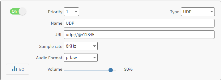
UDP
The UDP source type allows to receive a RAW UDP stream, i.e. to receive the stream generated from a legacy Annuncicom device.
The configuration is quite straightforward:
|
URL |
The UDP Address where the device has to connect to in order to receive the audio stream. It supports multicast or unicast addresses. Multicast URL scheme: udp://<ip>:<port> Unicast URL scheme: udp://@:port - When using unicast the device waits for incoming audio on the specified port. The “@” symbol is used to indicate the self-IP address of the IPAC device. |
|
Sample rate |
The sample rate of the stream to be played. It must match the sender setting. It allows:
|
|
Audio format |
The audio format of the stream to be played. It must match the sender setting. It allows:
|
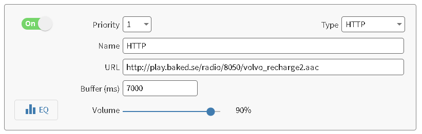
HTTP(S)
The most used protocol adopted by web radios to stream music via Internet. Enabling an IPAC device to connect with a music streaming provider via HTTP(S) transforms the device into a compact and reliable music streaming player. IP Audio Client supports also HTTPS connections to guarantee a secure connection with the music streaming server. Icecast or Shoutcast generated streams are fully supported.
|
Item |
Description |
|---|---|
|
Protocol |
|
|
Buffer |
Sets the playout buffer. (configure a range between 2000 ms-120000 ms)
Note: playback starts only after filling the buffer. I.e. if the buffer is set to 120000ms the playback starts only after 2 minutes after applying the setting. |
Configuring an HTTP Source is as simple as entering the URL of the web streaming server the IPAC device has to connect to.
|
Supported stream playlist types |
Description |
|---|---|
|
M3U / M3U8 |
Web streaming server providing an M3U or M3U8 (used mainly to play HLS streams) playlists containing stream URLs are supported.
|
|
PLS |
Web streaming server providing an PLS playlist containing stream URLs are supported.
|
When an HTTP(S) source is playing the Speaker Status reflects the playback status. The play count is an indication of how many times the device reconnected with the streaming server.

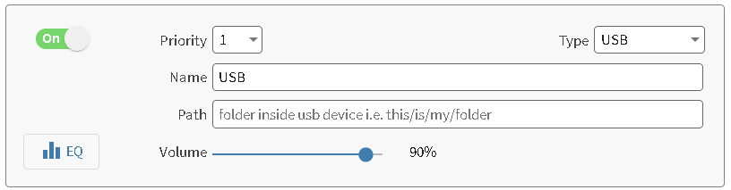
USB
This source is only available on devices with a USB port available. Its goal is to allow an easy way to play music (background music) from files stored on the USB pen-drive or stored and signed on a .m3u playlist.
|
Path |
path to a specific music folder inside the pen-drive i. e. /my_music/pop_playlist/ . Leave this empty to use the pen-drive base path (the root folder of the pen-drive). In absence of a .M3U file in the path the playback sequence is SHUFFLED. When an .M3U file is present, it is possible to specify the sequence of playback, where each line in the .M3U corresponds to the title of the song to be played, the sequence of playback is from top to bottom. The title must include the extension (i.e. "mySong.mp3"). |
Note: the application will be restarted if the pen-drive is unplugged. Reboot the device before insert the pen-drive again, hot plug n play is not supported.
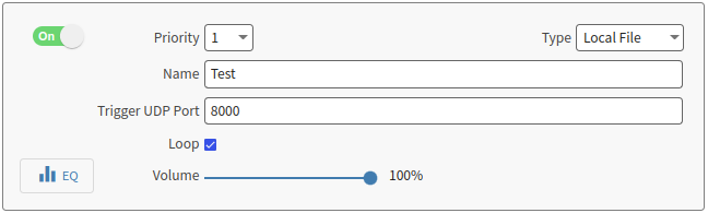
Local File
This source enables the user to play a locally stored file to play when the IPAC device receives a command via UDP at the configured port or via the IP Audio Client API call to play a local file.
On an IPAC device it is possible to upload individual audio files in the Audio Files tab or to connect a USB stick, in this case the files must be stored in a folder called “triggered_files” in the USB memory stick (if the IPAC device in use offers physical USB ports). Every audio file stored in the internal memory or from a USB external memory can be triggered to play using the “Local File” source. The working principle of this source type is to configure a port number between 8000 and 8999, IPAC will listen for a command on that port, when received it will immediately play the audio file specified in the command.
Trigger an Audio File from UDP
The datagram of the message required to play the file is:
FILEPLAY=fileName.xxx
This command has to be sent at the <IPAC_IP>:[Configured_Port] via UDP.
Replace “fileName.xxx” with the name of the file that has to play, “xxx” is the extension format e.g. “mp3”.
To STOP the playback send this command
FILESTOP
The commands must always be sent to the configured UDP port in the Local File source.
When the command is sent from a script running on a third party machine double check if it’s required to add the escape character “\n” at the end of the command. E.g. when sending the command from a Barionet device running a Lua script the command written in the script has to be: FILEPLAY=fileName.xxx\n
Here is a nice example on how to trigger the playback also from Windows and Linux machines.
Supported audio file names: "myFileName.ext" or "myFile Name.ext" - special characters are not allowed and maximum one space character in the name. Two or more spaces are not allowed. Files will fail to upload when not respecting the format expected
Supported audio files formats are: .mp3, .aac, .flac, .ac3, .dts, .wav, .ogg
Scheduler
The scheduler source is used to run the scheduled items configured in the Scheduler page
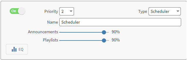
The scheduler embeds 2 different types of assets:
-
Announcements: short audio clips, either fixed time or rotational
-
Playlists: typically music tracks, arranged in playlists
In the source configuration it is possible to set the volume of the 2 asset classes independently. The change is applied in real time.
Scheduler Configuration
Before tests always check that date and time are correct.
In order to run a scheduler, there must be one configured. Locate the Scheduler tab in the top navigation bar. IP Audio Client offers 3 types of scheduler:
-
Fixed Time
-
Rotation
-
Playlist
All the schedulers work on a weekly basis.
The 3 types of schedulers can play simultaneously by the same scheduler source, for this reason they respect an intrinsic priority:
-
Fixed Time and Rotation: in case there is a Fixed Time announcement and a Rotation message set to play at the same time, the files are queued, the fixed time announcement plays first and the rotation plays after.
-
Playlist: music scheduled in the playlist scheduler plays always in absence of any announcement scheduled. Announcements always play on top of any scheduled playlist. Meant to be used as a BGM material.
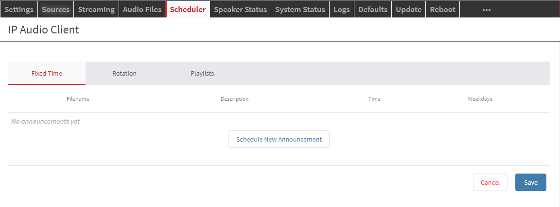
Fixed Time
This type of scheduler is suitable for announcements that must be scheduled to play at a specific fixed time of the day. E.g. bells or informative messages.
To create an new announcement:
-
Click on the "Schedule New Announcement" button.
-
The dialog the shows up allows to select a file from the ones already uploaded in the Audio Files tab OR to upload a new file to be used right in the Fixed Time Scheduler.
-
A description can be added (not mandatory).
-
Set the Play Time by typing the time manually or using the time picker, select the days of the week when the announcement must play and SAVE.
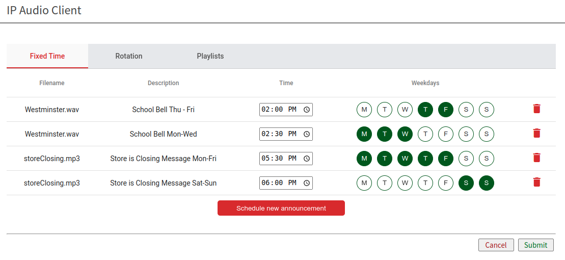
Announcements created appear as a list. They can be modified at any time using the provided controls:
-
Time: change the time when an announcement is scheduled to play.
-
Weekdays: change the weekly days when the announcement must play.
-
Edit: used to change a scheduled file and the description.
-
Copy: copy and paste an announcement on the next line to quickly setup the same announcement to play on different time and days.
-
Remove: remove a scheduled announcement.
Once the scheduler is complete use the SUBMIT button to confirm and apply the scheduler configuration.
Rotation
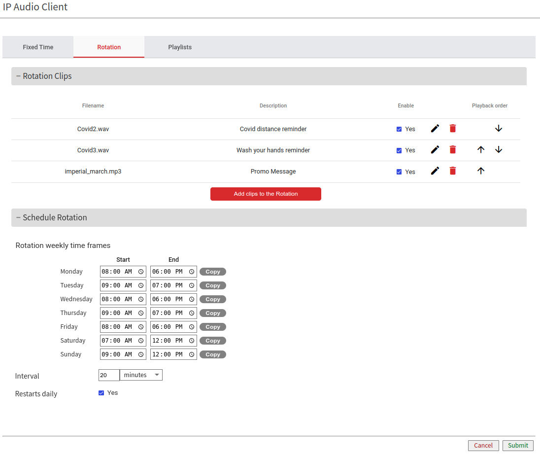
This type of scheduler is suitable for advertisements or messages to be played following a rotational pattern. To create a new rotation:
-
Add clips to the Rotation using the corresponding button
-
Configure the order of playback for the files added to the rotation, which file has to be the first, the second, etc.
-
Use the enabled/disabled flag to temporary disable a clip in the rotation (i.e. if an ad for chocolate bars is playing in the shop but the inventory for chocolate bars is out of stock).
-
Any clip in the rotation can be modified any time with the pencil icon or removed with the bin icon.
Once clips are in the rotation it's time to schedule the rotation:
-
It is possible to set a time window for each day of the week when the rotation starts and ends.
-
Use the copy buttons if the time frame is the same across multiple days.
-
Set the interval of playback, which is the time in between every clip part of the rotation. E.g. Interval is set to 15 minutes. The first clip will play, the second clip will play after 15 mins, the third clip after 15 mins, etc.
-
Restarts daily forces the rotation to start always from the first clip every day.
Once the scheduler is complete use the SUBMIT button to confirm and apply the scheduler configuration.
Playlist
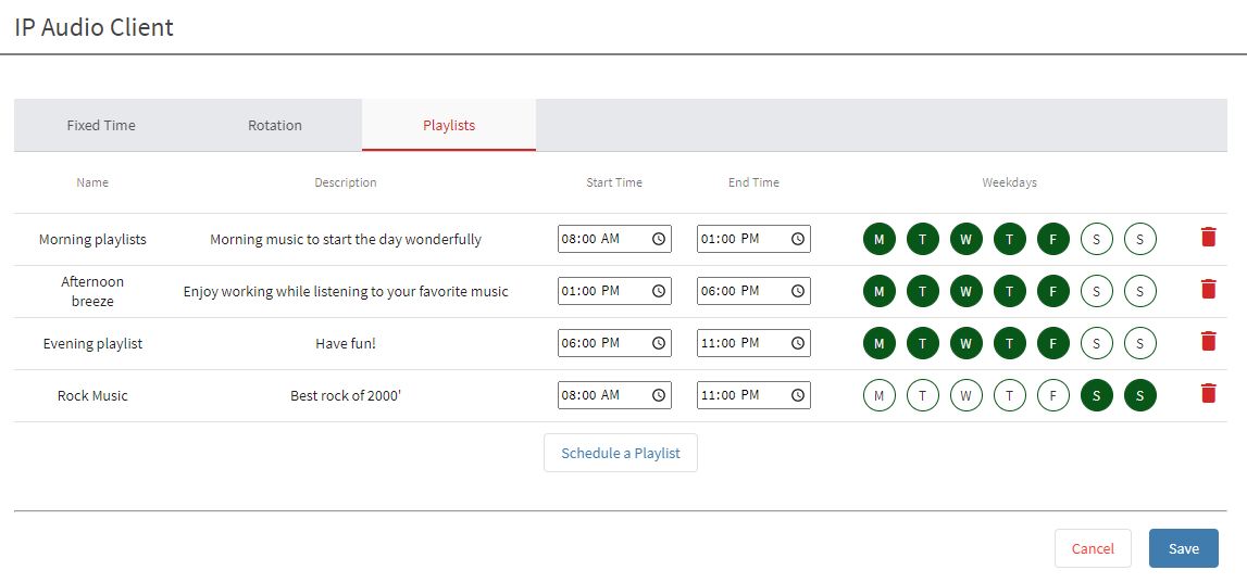
This type of scheduler allows the possibility to schedule playlists of files.
Before scheduling a playlist it is necessary to create one in the Audio Files Playlist tab.
How to create a playlist schedule:
-
Click on "Schedule a Playlist" to create a new playlist.
-
Select the playlist (retrieved from the playlists created in the audio files playlist tab).
-
Set the time window when the playlist must start and when it has to stop. Use the time picker or manually type the time in the fields.
-
Select the days when the playlist must play and click on "SAVE" to confirm.
The list of scheduled playlists shows all the currently scheduled items.
It is possible anytime to modify the start time, end time and the weekdays of the scheduled playlist.
Use the bin icon to remove a playlist from the scheduler configuration.
Once the scheduler is complete use the SUBMIT button to confirm and apply the scheduler configuration.
Dante® (source)
This source type allows to use the IPAC device as a 2 channels Dante® receiver.

Dante® License
Dante® requires a license released by Audinate Pty Ltd. in order to run on IP Audio Client. Make sure to order the right PN when purchasing the IPAC device. It is not possible to install a Dante® license on a device that was manufactured without it.
The routing of the audio sent to IPAC is managed in the Dante® Controller where the device, by default configuration, appears with the name “barix-<last_6_digits_MAC>” (i.e. “barix-09cfab”). It is possible to change the name in the device config section inside the Dante® Controller. Below is an example of IPAC devices receiving a 2 channels Dante® stream from a Dante® AVIO 2x0 (2 channels analog input adapter):
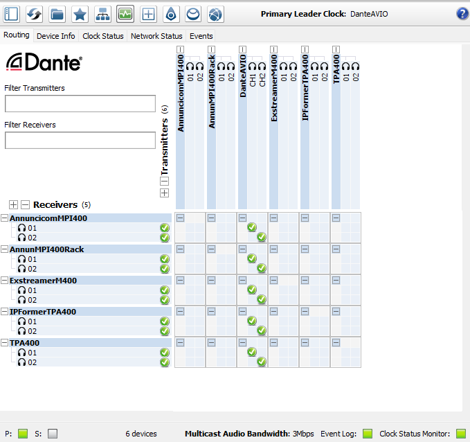
Most of the monitoring and reporting is also achieved inside the Dante® Controller in the Device Info, Clock Status and Network Status tabs.
Sample Rate and Encoding Format adjustments are performed on a device basis in the Dante® Controller. Double-Click on the interested device in the routing pane, a new window appears, locate the ‘Device Config’ tab:
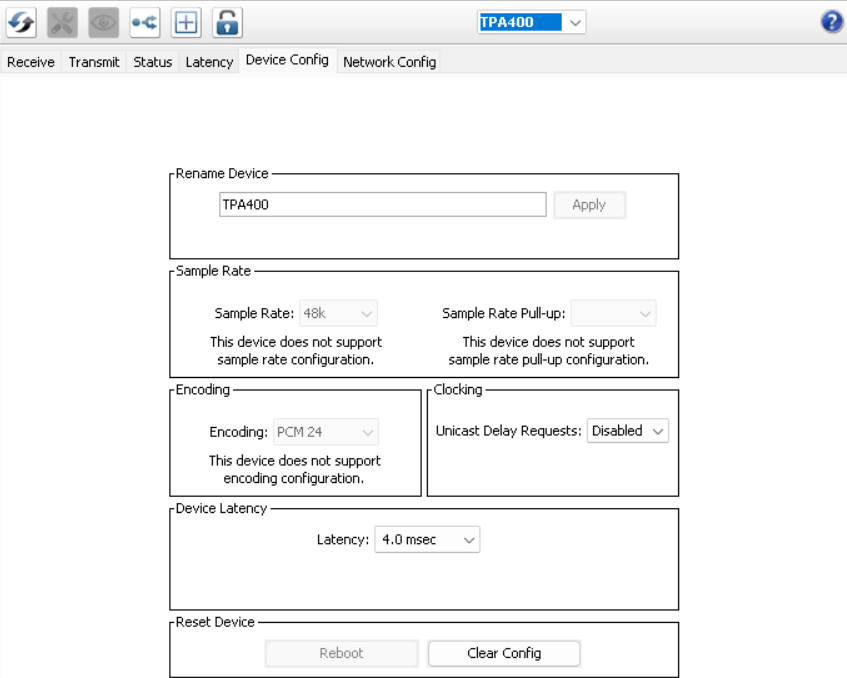
IPAC devices allow a sample rate of 48 kHz, while the encoding format is 24 bits.
Warning about Latency
The Dante® implementation on IPAC targets a flexible usage of the device which allows to combine multiple sources assigned at different priority layers. Due to the nature of this architecture the IPAC Dante® receiver plays with a higher latency compared to other Dante® enabled products, the latency reported in Dante® Controller doesn’t include the latency added by the IPAC decoder chain. Key applications for IPAC Dante® devices: BGM distribution, paging over Dante®, Dante®-SIP bridging, Dante®-RTP bridging, all 'non-live' applications.
For more information on Dante® Controller and all the features offered please check the Audinate’s website here
To download Dante Controller visit Audinate’s website here
Useful Links from Audinate’s website: Audinate FAQs - Network Requirements and other useful information
Audio Files
Audio Files can be stored in the internal memory of the device or they can be played from an external USB memory storage connected to the front panel USB ports (for IPAC devices supporting the USB feature). The audio files page is where the user can upload files or check files present on an external USB memory.
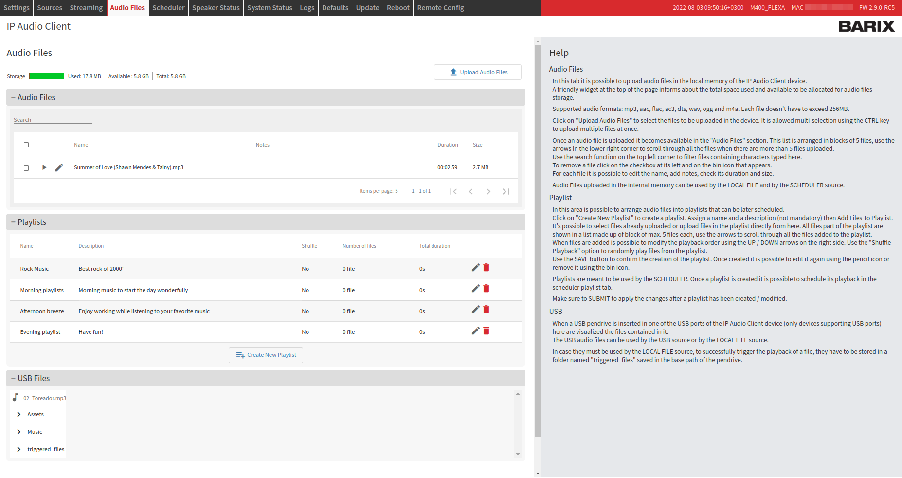
The page is organized as follow:
-
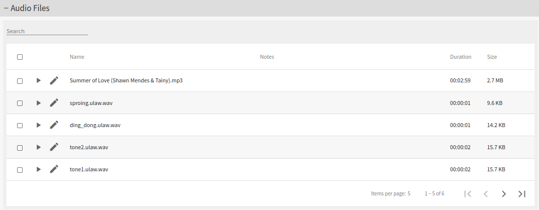
Audio Files: List of audio files already stored in the local memory of the device. The maximum number of files that can be uploaded depends on the available memory available. A useful widget in the top of the page helps monitoring the amount of space being used
-
Playlists: Here is where audio files can be arranged into playlists, or group of files that can be playback following a sequence
-
USB Files: If a USB pen-drive is attached to one of the USB ports of the IPAC device, its content is listed here.
Internal Audio Files
In order to upload audio files click on "Upload Audio Files" to select the files to be uploaded in the device. It is allowed multi-selection using the CTRL key to upload multiple files at once.
-
Once an audio file is uploaded it becomes available in the "Audio Files" list. This list is arranged in blocks of 5 files, use the arrows in the lower right corner to scroll through all the files when there are more than 5 files uploaded. Use the search function on the top left corner to filter files containing characters typed here
-
To remove a file click on the checkbox at its left and on the bin icon that appears right after
-
For each file it is possible to edit the name, add notes, check its duration and size
-
Preview function: clicking on the PLAY button on the left side of the filename will preview the file, the playback will start immediately on top of anything that is being currently playing by the IPAC device.
Individual file size when uploading in the internal memory: 256MB
Supported audio files formats are: .mp3, .aac, .flac, .ac3, .dts, .wav, .ogg
Playlist
In this area is possible to arrange audio files into playlists that can be later scheduled.
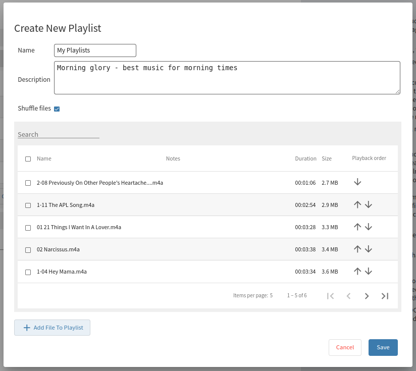
To create a playlist:
-
Click on "Create New Playlist" to create a playlist.
-
Assign a name and a description (not mandatory)
-
Add Files To Playlist. It's possible to select files already uploaded or upload files in the playlist directly from here.
-
All files part of the playlist are shown in a list made up of block of max. 5 files each, use the arrows to scroll through all the files added to the playlist.
When files are added is possible to modify the playback order using the UP/DOWN arrows on the right side. Use the "Shuffle Playback" option to randomly play files from the playlist.
Use the SAVE button to confirm the creation of the playlist. Once created it is possible to edit it again using the pencil icon or remove it using the bin icon.
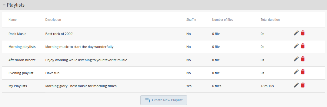
Playlists are meant to be used by the SCHEDULER. Once a playlist is created it is possible to schedule its playback in the scheduler playlist tab.
Make sure to SUBMIT to apply the changes after a playlist has been created / modified.
USB Files
This section in the Audio Files tab is present only if a USB pen drive with valid content is attached to the IPAC device.

The list of folders and files is available for the user to scroll.
To play USB files using the LOCAL FILE source, which triggers the playback via UDP or REST API, ensure that the files are stored in a folder called: triggered_files
Check Local File Source and USB source details for more information
Handle USB pen drives
When using external USB memories it’s possible to attach them to the USB port while the device is either powered on or off but to eject or remove a USB there is no “Eject” function available, thus is necessary to power off the IPAC device and remove the USB afterwards, this will ensure no files on the USB will be corrupted.
Streaming
In the streaming tab are present the configuration options to stream the MAIN audio output (with all intrinsic source configuration) to network destinations via RTP or Dante® (only for licensed devices).
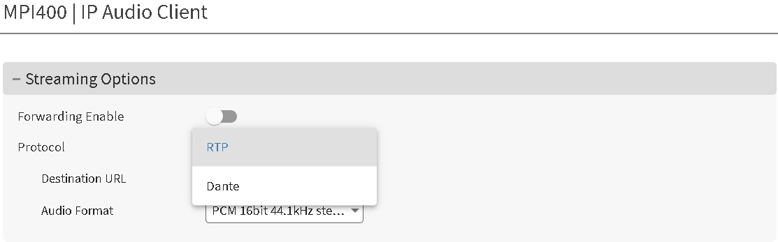
Dante® Forwarding
It allows to stream the main output to Dante®, thus enabling the IPAC device to become a 2 channels Dante® transmitter.
Dante® License
Dante® requires a license released by Audinate Pty Ltd. in order to run on IP Audio Client. Make sure to order the right PN when purchasing the IPAC device. It is not possible to install a Dante® license on a device that was manufactured without it.
When the Dante® Forwarding is enabled on an IPAC device, its local audio output is muted and the audio routing is fully managed by the Dante® Controller. In the picture below is an Annuncicom MPI400 streaming to other IPAC devices with a Dante® source configured to receive the stream.
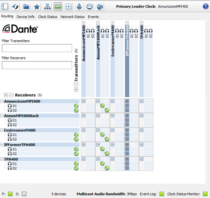
This functionality allows to use an IPAC device as a 'Dante® gateway' since it is possible to setup multiple sources like: Paging, InformaCast, SynApps, SIP, Scheduler etc.. and send the output to a Dante® system.
These are all the possibilities available:
-
RTP: IPAC to receive an RTP stream and forward it to Dante®
-
InformaCast: IPAC to receive an InformaCast notification and forward it to Dante®
-
SynApps: IPAC to receive a SynApps notification and forward it to Dante®
-
Scheduler: IPAC to run a message/bell/ads/BGM scheduler and forward it to Dante®
-
SIP: IPAC to receive a SIP call and forward it to Dante® / IPAC to feed a SIP call with Dante® audio => This allows for remote bidirectional interconnection of 2 Dante® systems.
-
UDP: IPAC to receive an UDP stream and forward it to Dante®
-
USB: IPAC to play from USB and send its audio to Dante® (simple USB BGM solution to Dante®)
-
HTTP: IPAC to receive an HTTP stream from a web radio and forward it to Dante®
-
Paging: IPAC to receive an IC Paging / Simple Paging stream and forward it to Dante®
-
Local Files: IPAC to play local files triggered via API and forward to Dante®
Of course it’s possible to combine multiple sources (up to 5 layers can be configured in IPAC) and the whole output can be forwarded to Dante®.
RTP Forwarding
This function forwards the MAIN audio output of the IPAC device to a configured destination via RTP. Other IP Audio Client devices in the same installation can play the content forwarded by this IP Audio Client. This enables the creation of setups where one IPAC device (e.g.) operate as a “gateway” running multi-source configurations like: InformaCast, SIP, Paging, RTP, HTTP and all its traffic is then routed back in the network to other IPAC client devices.
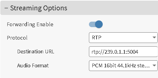
If the destination URL is a mutlicast address the IPAC device will become a client of itself, it will join the same RTP stream it forwards and will play it at the analog audio output.
If the destination URL is a unicast address this IPAC device will go silent and will only stream its output to the destination URL.
|
Item |
Description |
|---|---|
|
Enable/Disable |
Enables or disables the RTP Forwarding function |
|
Destination URL |
The destination IP address where to forward the stream over RTP. It can be a Multicast/Unicast IP Address with the "rtp://" and the port number specified i.e. "rtp://239.0.1.1:5004" |
|
Audio Format |
It is possible to choose the audio format of the forwarded stream among:
|
When playing an RTP stream forwarded by an IPAC device on other IPAC units in the same installation, the end to end delay is approximatively 190ms and the playout across different devices is in sync.
Inputs/Outputs
This page is presented only on devices offering digital inputs and digital outputs or relay outputs hardware support. (e.g. Annuncicom MPI400).
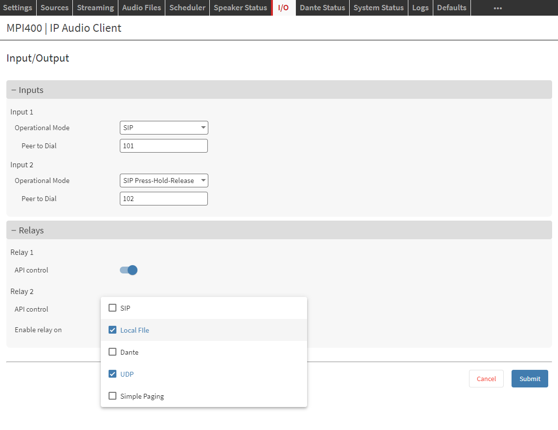
Inputs
This section allows the configuration of the Digital Inputs (dry contacts). For each Digital Input physically detected on the device it is possible to independently set:
-
Operation Mode
-
SIP: When the contact is closed, the input state is lowered and a call to the configured peer is initiated. The input can then go back to its initial state. To hangup the call the input must be closed one more time.
-
SIP Press-Hold-Release: When the contact is closed, the input state is lowered and a call to the configured peer is initiated. The call is kept open until the input state doesn't change, when this happen the call is closed.
-
Calling:
-
[Press] Input goes high (1) => Call is started towards the destination defined
-
[Hold] Input stays high (1) => Call is held
-
[Release] Input goes low (0) => Call is closed
-
-
Receiving:
-
[Press] Input goes high (1) => Call is picked up
-
[Hold] Input stays high (1) => Call is held
-
[Release] Input goes low (0) => Call is closed
-
-
-
SIP Refer Blind Transfer: In this mode the Input can be used to transfer the ACTIVE call to the configured "Peer to Dial". For this to happen the call must be ACTIVE. SIP Blind Transfer (RFC5589) doesn't check for the availability of the remote peer where the call is being transferred, it simply transfers the call as soon as instructed by the Digital Input state. When the Input is closed and used to Blind Transfer the call, the ACTIVE call is closed and transferred.
-
If your PBX or SIP Server already have Forwarding rules configured they can affect the functionality of SIP Refer Blind Transfer.
Not all the SIP Servers support this mode.
Peer to Dial: Is the remote party, the peer to be called when the input is closed. When SIP Source is configured in "Peer to Peer" or "Server and Peer to Peer" it's possible to dial an IP ADDRESS. When in "Server" or "Server and Peer to Peer" mode it is possible to dial a SIP Extension that belongs to the same domain.
-
Receiving Calls
-
When a Call is received and SIP Auto Answer is ENABLED (see SIP Source Advanced configuration): any Digital Input can be used to close the active call
-
When a Call is received and SIP Auto Answer is DISABLED (see SIP Source Advanced configuration): any Digital Input can be used to pick up the call, consequently any Digital Input can be used to close the active call.
-
Relays
This section allows the configuration of the trigger detection to change the current state of the relays. Consult the User Guide of the HW device being used to verify the default state of each relay.
E.G. on Annuncicom MPI400 the default condition is:
- Relay 1: Normally Opan
- Relay 2: Normally Closed
For each Relay is possible to specify the trigger condition as follow:
-
Enable Relay On: this option offers an easy way to select which source, among the ones configured in the sources tab, will control the relay when it is activated (i.e. when there is an incoming audio)
-
API Control
-
It allows the possibility to enable the control of the corresponding relay via REST API. The API control is independent from any other control that might be already assigned to the Relay.
Check the API documentation for more details.
-
Intercom
This tab is presented only on devices supporting Intercom Stations functionalities. E.g. Annuncicom AHE YA404
IPAC devices implementing this feature present multiple “Station” outputs (up to 16 for the Annuncicom AHE YA404), each one supporting an Intercom panel. Typical applications:
-
Paging / intercom device for classrooms, hospitals, elevators, factories, public transportation, prisons etc.
-
Door Intercom station
-
Help Point/SOS call box device
-
Generic, bidirectional half-duplex VoIP module for Paging and Intercom applications

The system operates using two distinct audio channels, each serving specific communication functions:
-
Paging Channel (the output of the sources configuration)
The Paging Channel serves as the default audio output for all stations when no active SIP intercom calls are in progress. This channel continuously broadcasts audio content configured through the SOURCE tab in the web interface. Common applications include background music, announcements, or ambient audio distribution to all connected stations.
-
Intercom Channel
The Intercom Channel activates when a station initiates communication with the central station. This channel takes priority over the Paging Channel and is configured through the Intercom tab in the web interface. The system supports a maximum of one station on the intercom channel at any given time and uses SIP to establish connections with a remote central.
Intercom Operation Characteristics
Audio Direction Control
When a station is connected via the intercom channel, audio transmission operates in half-duplex mode. The direction of audio flow is automatically determined by audio presence detection at the central station:
-
Station-to-Central: When no audio is detected from the central station, the station's speaker functions as a microphone, transmitting room audio to the central station.
-
Central-to-Station: When audio is detected from the central station, it takes priority and is transmitted to the station's speaker.
Dynamic Role Switching
The station's speaker unit dynamically switches between output (speaker) and input (microphone) modes based on the communication direction, enabling natural two-way conversation flow.
Typical Operation Workflow
Standard Operation Sequence
-
Default State: All stations receive audio from the Paging Channel (e.g., background music from an HTTP / RTP source or announcements from a Scheduler source).
-
Call Initiation: A user activates the station's input mechanism to initiate communication with the central station.
-
SIP Call Establishment: The system establishes a SIP call between the requesting station and the designated central extension.
-
Initial Communication Phase:
-
The central station is initially muted upon call connection
-
The station's speaker operates as a microphone, transmitting room audio to the central station
-
Central personnel can hear audio from the requesting station's location
-
-
Bidirectional Communication:
-
When central station personnel speak, the station's speaker returns to output mode
-
Audio from the central station is transmitted to the requesting station
-
Communication continues with automatic direction switching based on audio presence
-
-
Call Termination: Upon call completion, the station automatically returns to receiving audio from the Paging Channel.
Group Paging
By configuring a SIP Source in the SOURCES tab it will be possible to use a dedicated extension for an ALL station page.
When doing so, the channel used is the paging channel which drives ALL stations with the same signal.
It is NOT possible to perform a group page for a subset number of stations.
Intercom Settings Configuration
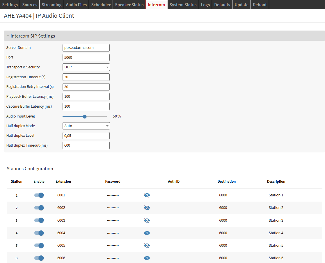
|
Item |
Description |
|---|---|
|
Intercom SIP Settings |
|
|
Server Domain |
The server url or IP Address that the IPAC device has to register with. It can be the server hostname or the IP Address Default: “empty” |
|
Port |
Allows to configure the SIP negotiation Port Default: 5060 |
|
Transport & Security |
Allows to configure the transport and security protocols to be used to establish the connection and transport data:
Default: UDP |
|
Registration Timeout |
Configure the interval used for the registration with the SIP Server, in seconds.
Default: 30 |
|
Registration retry interval |
Configure the registration retry interval in case of registration failure, in seconds. Set to 0 to disable auto re-registration.
Default: 30 |
|
Playback Buffer (ms) |
Sets the desired target buffer for the SIP playback interface. An higher value increases the overall delay gaining on quality, a lower value decreases the delay but the quality of the play-out might be affected by drops or errors. Default: 100 |
|
Capture Buffer (ms) |
Sets the desired target buffer for the SIP capture interface. An higher value increases the overall delay gaining on quality, a lower value decreases the delay but the quality of the play-out might be affected by drops or errors. Default: 100 |
|
Audio Input Level |
Fine tunes the audio input level to increase or reduce the input level into the SIP call. Default: 50% |
|
Half Duplex Mode |
The Intercom Channel only operates in Half Duplex, that means it doesn’t allow to transfer audio in both directions at the same time. Auto: The “direction” of the audio in the call is prioritized based on audio detection of the remote central. When no audio is detected, the direction is “station” → “central”, when audio is detected and goes above the specified “Level” (see below) the audio direction switches and is from “central” → “station” Manual: The direction of the audio is controlled by the digital input (button pressed) on the station. As far as the button is pressed the direction is “station” → “central” when button is released the audio is from “central” → “station”. in this configuration the call can only be ended by the remote central. Default: “Auto” |
|
Half Duplex Level |
This is a “threshold” value between 0 and 1 that helps to fine tune the level at which the audio detection on the remote central happens to switch the direction of the audio. When set to 1, the behavior is similar to a FDX communication. This is not used when Mode is set to “Manual”.
|
|
Half Duplex Timeout |
After remote central takes priority in the call (audio goes above the specified level) this is the timeout to be configured before the direction is switched back when audio goes below that same level. It accepts values from 10 to 1000 ms.
|
|
Station Configurations - each station is registered in the SIP server with a dedicated extension |
|
|
Enable |
Enable / Disable the corresponding station |
|
Extension |
The extension / username to be used for the corresponding station |
|
Password |
The password to be used for the corresponding extension |
|
Auth ID |
The Auth ID to be used for the corresponding extension |
|
Destination |
The extension to be dialed when the input is closed (button pressed) |
|
Description |
A brief description of the station |
Remote Configuration Tool
A useful tool to manage multiple IPAC devices installed in the same network. The remote configuration tool is a server-less program. Every IPAC device runs a backend able to automatically find other IPAC devices on the network using the Avahi service and list them in this page. Avahi is built relying on mDNS and DNS-SD which takes advantage of multicast properties to advertise services on the network and enable connections between machines. IPAC devices advertise the services on the IP address: 224.0.0.251 (IPv6 ff02::fb) port 5353 (as per mDNS specifications). Below is a video introduction and explanation on the configuration tool (it refers to IP Former but the video is valid for all other IPAC devices too), where it is possible to see it in action.
The Remote Configuration Tool lists only IPAC devices running the same firmware version
The goal of the remote config tool is to facilitate and speed up the configuration of an entire system, particularly useful in case of IP Former installations, where each (IP Former) loudspeaker is an endpoint of the system and it might be easy to have tens of devices into the same installation. Thus it avoids the need to log into every single web interface to perform a configuration but access only one device to configure the entire system. On any IPAC device when opening the Remote Config tab will show:
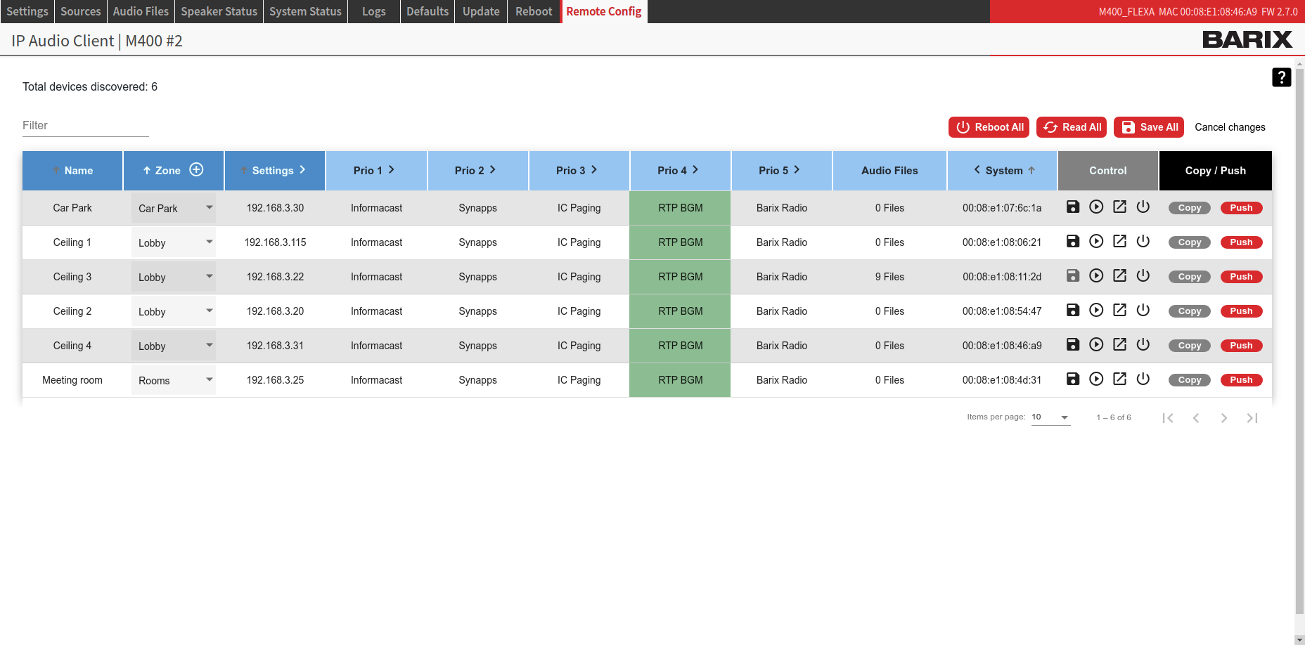
The table is organized in columns, some of them are dynamic, meaning it is possible to open their content to change configurations (note the small arrow on the right-side of the header). Above the table, in the upper section of the screen there is an indication on the Total number of devices discovered and a search bar that can be used to filter the content of the table. By default the table visualized sorts the devices by their Zone name. A green marker around a source (the one in the RTP BGM in the screen above) indicates that the source is (or was) playing the last time the Remote Config Tool table was refreshed, the marker is not updated in real-time but after a table reload (or clicking on the READ ALL button).
|
Function |
Description |
|---|---|
|
Name |
This is the name used in the web interface and in the configuration tool to identify a device. By default is set to “Empty”. To change it click on the pencil tool that appears in proximity of the name cell when overlaid with the mouse. Once modified SAVE. Change table sorting: in the Name column header there is an arrow, click on it to change the sorting using the device’s name from A -> Z to Z -> A. |
|
Zone |
It is possible to assign devices to Zones. This makes it easy to apply the same configuration only to devices that are part of the same Zone. By default this field is set to “Zone 0”, all new discovered devices are part of this default zone and can be controlled in bulk immediately. Add a new Zone: click on the plus-circled button on the header of the zone column. This will open a dialogue window where you can check the list of the already existing zones and add a new one simply typing the name of the new zone to be added and click on Add 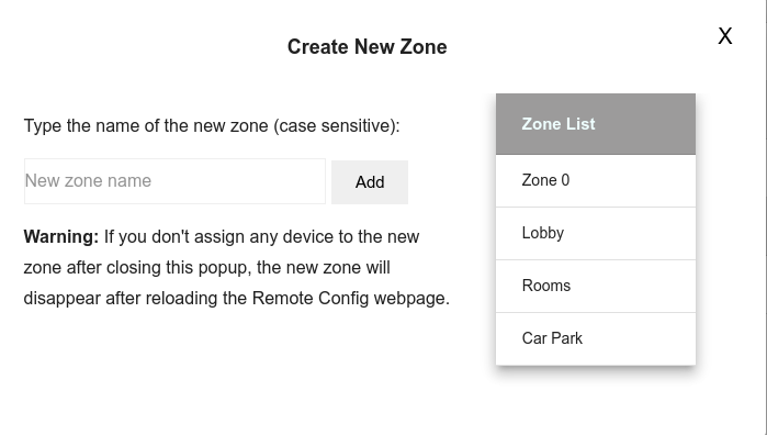
Rename a Zone: simple overlay with the pointer the zone name of any device part of the Zone and click on the pencil tool that appears then confirm the change by pressing the “V” confirmation button, the new name will be applied automatically to all devices belonging to that zone. 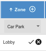
Assign devices to Zone: select the zone from the drop-down menu in correspondence of the device required, after selecting the new zone a dialogue window asks if the change has to be applied only to that device or all devices part of the same Zone. Selecting NO will only assign that device. Selecting YES will change all devices. 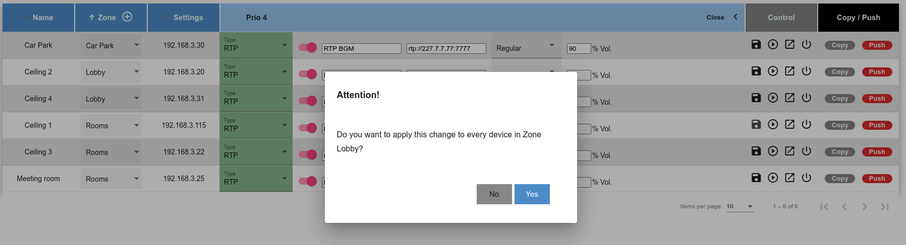
Remove a Zone: there is no such function in the Remote Config Tool. A zone is removed automatically when no devices are part of it. If it’s still available in the drop down is because the web page needs to be refreshed, the zone containing no devices will disappear from the list right after. Change table sorting: in the Zone column header there is an arrow, click on it to change the sorting from A -> Z to Z -> A. |
|
Settings |
This is a dynamic column. Click on the arrow in proximity of the Settings header to open the device's settings configuration 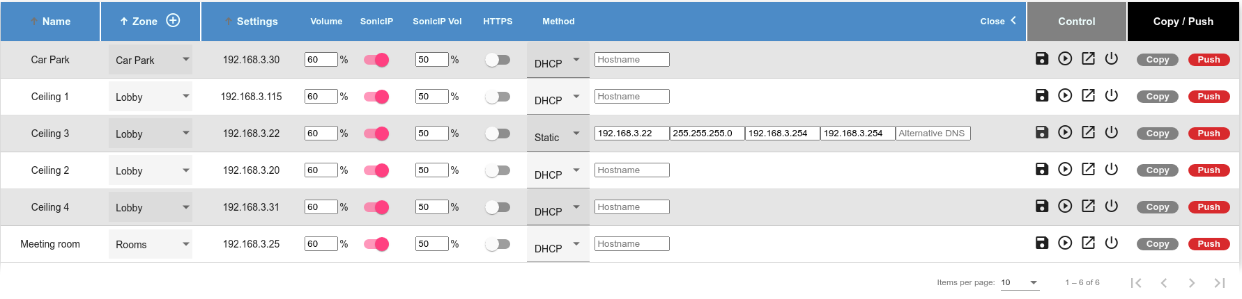
For each device it is possible to (from left to right):
These are the same Settings available in the Settings page of each IPAC device. For more help topics on each field refer to the help section of the Settings page. When settings are changed it is important to SAVE them with the corresponding buttons in the device control section or using the SAVE ALL button available in the top right corner of the page. |
|
Priorities |
These are 5 dynamic columns reflecting the priority layers also available in the source tab. Click on the arrow in proximity of the header to expand the desired priority layer and configure the source, the parameters and values available are the same as the ones available for each source described in previous chapters. below is an example of InformaCast source expanded: 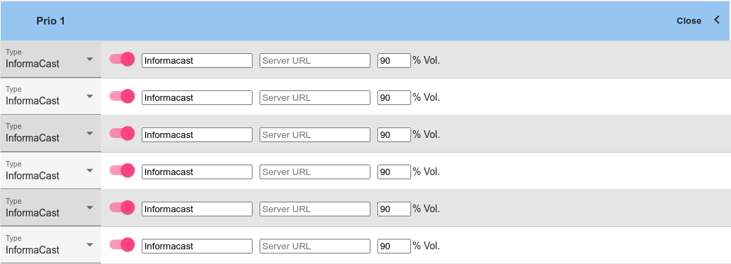
Every priority layer will allow the user to:
|
|
Audio files |
This column simply visualizes the number of audio files uploaded and stored. Visit the Audio Files section (or Local File source chapter) for more information on how to handle audio files playback |
|
System |
This is an expandable column that opens up the details of the IPAC devices: MAC Addresses, HW Type, FW Version installed, System Time, Up TIme (since how long the device is powered), License (if the device contain any valid license, i.e. Informacast). 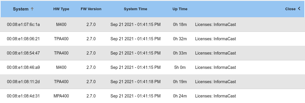
|
|
Control |

From left to right:
|
|
Copy/insert |
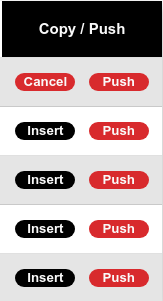
COPY / INSERT: copies the whole configuration of a device to other devices. When clicking on copy on one device, all copy buttons of the other devices will transform in an INSERT button. Click on as many INSERT as needed to apply the same settings of the COPIED device on the desired devices. The Copy function will allow you to create custom installations where devices part of the same zone might have different configurations. Copy / Insert will only affect Sources configuration and not the settings. The Copy / Insert function requires to click on SAVE ALL in the top right corner of the page to apply the new configuration to the affected device(s) |
|
Push |
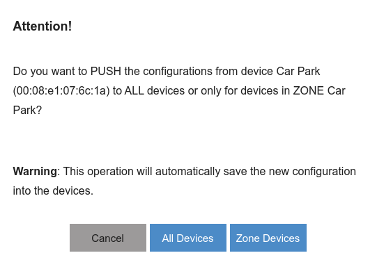
This function pushes the configuration of one device to all other OR to devices part of the same zone. A dialogue shows up after clicking the button allowing the user to decide. The “push” function is what actually speeds up large system configurations. After setting up one device it is possible to copy its configuration to all others in 2 clicks. Unlike the Copy / Insert function the configuration that will be replicated includes also the settings: Master Volume, Sonic IP, HTTPS enable/disable plus all priority layer configurations. On top of this the new configuration is automatically saved and applied to the devices |
|
Bulk Actions |
|
|
Reboot all |
Reboots all the devices discovered at once. It opens a dialogue asking for confirmation before proceeding. |
|
Read all |
The Read All button is used to parse the configuration of all IPAC devices in the network and refresh the table. If there are some pending changes not yet saved the user is warned as they must be either canceled or applied (saved) before refresh the table. When a new source configuration is applied, IPAC might take some seconds while restarting the services required to advertise itself and be identified by the remote config tool, in those occasions if the number of devices discovered is not the one expected, click on Read All so that the number is updated. |
|
Save all |
Saves any modification made in ALL the devices discovered. If no modifications are done, there is no operation performed and the user is informed. |
|
Cancel changes |
Cancels any modification performed in any device in the list and restores the initial condition |
Speaker Status
The Speaker Status page is the main dashboard of the IP Audio Client application. The window is quite essential , it displays the current playback status with the source arranged from top to bottom reflecting the priority layers. A green marker colors the currently playing source.
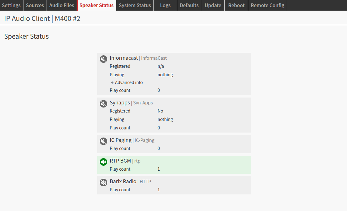
Each source contains the information related to the source itself and they change according to the status of the single source. A thorough description on how the speaker status changes for each source is given in the source chapter of this guide.
The Play count is a counter that shows the number of times the corresponding source played. The counters are reset every time a change in the source configuration is applied or after a reboot.
Dante® Status
Only present on Dante® Licensed devices
The Dante® status tab is where IPAC shows some important details on Dante®:
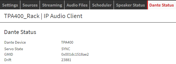
|
Dante® Device |
The name of the device assigned in the Dante® controller |
|
Servo State |
Indicates the clock status:
|
|
GMID |
The ID of the device providing the clock in the system, the PTP leader. |
|
Drift |
The drift between the leader and this device's clock (if this device is the leader the drift is 0) measured in microseconds |
The Dante® Status tab appears only on Dante® licensed devices
System Status
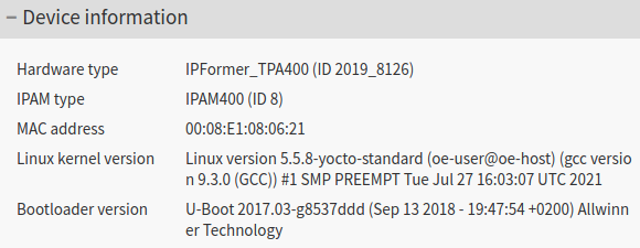
|
|
|
Hardware type |
The actual IPAC device hardware (in parenthesis is the Part Number) |
|
IPAM type |
The Barix IPAM codec module installed in the device (in parenthesis the ID of this component) |
|
MAC Address |
Media Access Control address - This is the hardware address of the Ethernet interface of the device |
|
Linux kernel version |
The version of the Linux operating system in use |
|
Bootloader version |
The bootloader version currently in use |
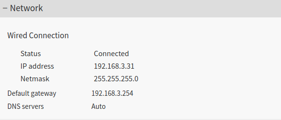
|
|
|
Status |
Shows if the device is connected via the Ethernet interface to the network |
|
IP Address |
The current IP address of the Ethernet interface |
|
Netmask |
The subnet mask on which the device is operating |
|
Default Gateway |
The gateway address currently set |
|
DNS Servers |
The DNS server addresses (primary and secondary) currently in use. Provided either by the DHCP or entered manually in the settings page |
|
|
|
System time |
The device's current local time |
|
Uptime |
How long the device is powered on |
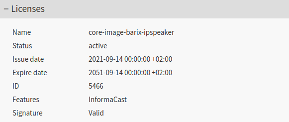
|
|
|
Name |
The name of the base license for the IPAC device |
|
Status |
Either if the license is active or expired |
|
Issue date |
The date when the license was issued |
|
Expire date |
The date when the license will expire |
|
ID |
The license unique identifier |
|
Features |
If this license has any additional features (e.g. InformaCast) |
|
Signature |
Either if the license that is running on the image is valid or invalid (in such case the application wont run) |
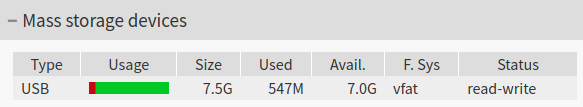
|
|
|
Mass Storage |
Shows up only if there is any USB external memory connected to the IPAC device providing the details of the same |

*Only available on IPAC devices with temperature sensor implemented in the amplifier (e.g. IP Former TPA400) |
|
|
Amplifier temperature |
Shows the current temperature of the amplifier. It updates at every page reload. |

*Only available on ceratain IPAC devices with automatic gain amplifier adjustment depending on the power available and impedance measurement feature (e.g. Exstreamer MPA400) |
|
|
Power Source |
The power source detected to power the IPAC device (PoE, PoE+, PoE++, 4PPoE or External Power Supply) |
|
Speaker Impedance |
The speaker load detected connected to the IPAC device’s terminals |
|
Amp Gain |
The amplifier output voltage (Vpp) capability |
Logs
The Logs page displays the events occurring operation of the IPAC device. Logs are useful for debugging issues, they give a detailed insight into every process within the OS. On the top-right corner, it is possible to click the button “Download all messages” to download all log files.
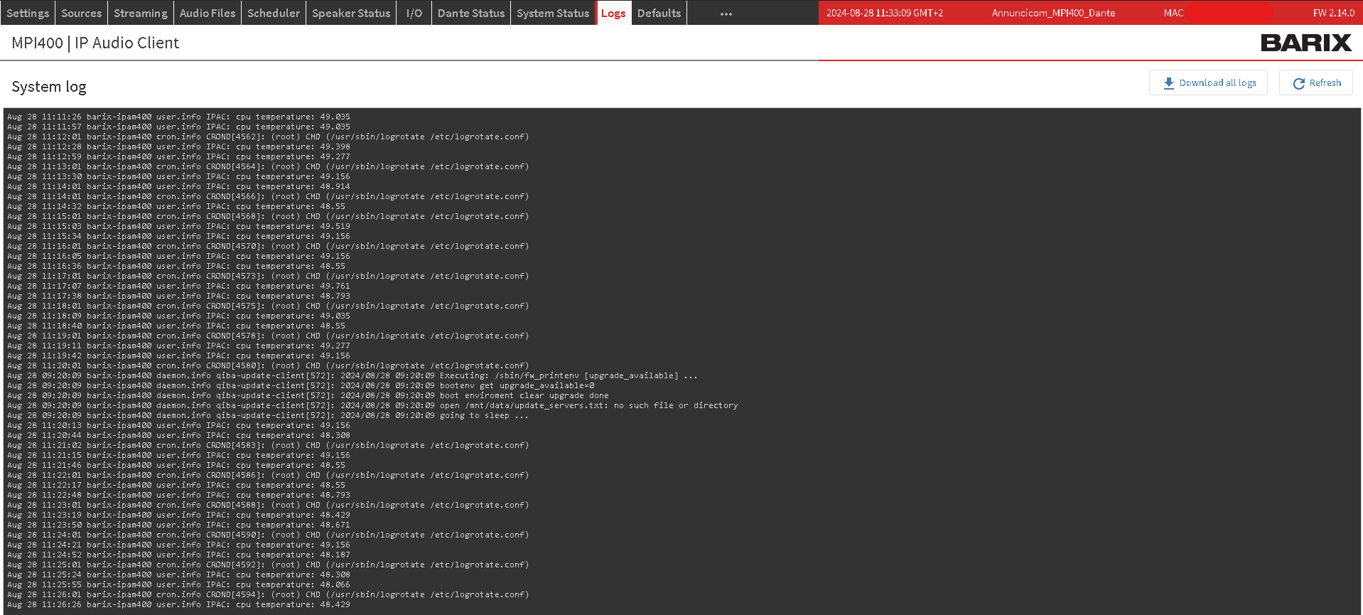
When contacting the Barix support it is useful to attach along with the communication the Log files downloaded and the status page screenshot. Do not forget to give a description as much detailed as possible about the steps made that led to the issue.
Packet Capture Procedure
Packet capturing is a powerful diagnostic tool that allows you to monitor and analyze network traffic. This feature is useful for understanding the data flow between hosts on your network. Follow these steps to initiate and retrieve a packet capture:
-
Initiate Capture
-
In the address bar of your web browser, append the following to the current WebUI URL:
/web/rest/v1/tools/start-interface-capture/eth0 -
Press Enter to execute the command.
-
-
Confirm Capture Initiation
-
Upon successful initiation, you will see a confirmation message:
"Capture started for interface [interface number] for 5 minutes or 5MB. Output will be available in [specified time]."
-
-
Retrieve Capture Data
-
After the specified time has elapsed, return to the main WebUI.
-
Navigate to the LOGS tab.
-
Download the complete log package clicking on the corresponding button
-
Locate the "captures" folder within the downloaded package to access your packet capture data (.pcap file, which can be opened with a software like Wireshark for detailed analysis)
-
The packet capture will automatically terminate after 5 minutes or when it reaches 5MB of data, whichever occurs first.
Defaults Page
Reset to factory defaults - Soft reset
The defaults page allows performing a soft-reset (it doesn’t change the device’s application mode). Such operation reverts all settings except the network settings back to factory defaults (it doesn't perform a firmware downgrade, just a reset of the settings for the running application). The reset to factory defaults can be enabled or disabled from the settings page, under "Security Settings".
When resetting to defaults the application mode is not changed. I.e. if the unit is running in AES67 Mode it will keep running in that mode after a reset.
Reset to factory defaults – Hard reset
It is also possible to perform a hard reset. A hard reset will revert all settings to factory defaults including the network settings.
To perform a hard reset locate the reset button on the front panel of the IPAC device and keep it pressed for approximately 10 seconds using a sharp-pointed tool while the device is powered. The status led will blink green 3 times, informing that the reset operation is started. After a few seconds, the device will reboot with factory defaults. Reload the page after the operation is completed.
When resetting to defaults the application mode is not changed. I.e. if the unit is running in AES67 Mode it will keep running in that mode after a reset.
Rescue Image Process
In some occasions it is possible that the application faces some issues that cannot be restored with a hard reset to default. In this situation a rescue image process might solve:
-
If your IPAC device is powered, shut it off
-
Make sure the device is connected to internet. For this process to work the device will attempt a connection to Barix Update Server (release.barixupdate.com), via HTTP (port 80), if successful it will download the rescue image from this server
-
While the device is off, press the reset button
-
Keep the button pressed while powering up the device
-
Keep the button pressed in for 8 seconds after the device is powered, then release
-
When the rescue process starts the led blinks orange
-
The device will restart indicating the FW install was successful
After this process the device will run the firmware image fetched from the download server.
Update
IP Audio Client offers the possibility to update the firmware of the device from this page and to program the automatic firmware update.
Run always the latest firmware available from Barix as it might include bug fixes, improvements or new useful features.
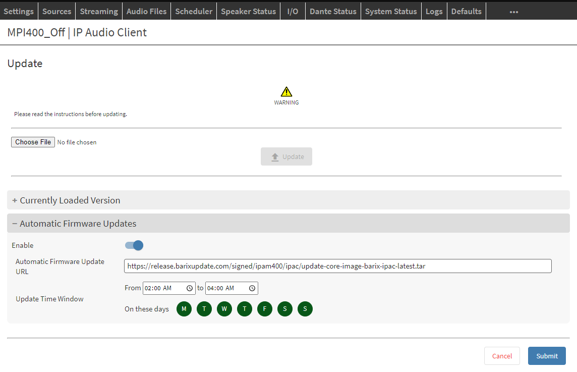
By default the Automatic FW update is disabled.
In the same page it is possible to visualize the current firmware version running and to manually update it.
Manual Firmware Update
|
1 |
Download the latest firmware from here - The firmware is a .tar archive. |
|
2 |
In the Update Tab Click on “Choose File”, locate and select the .tar archive just downloaded |
|
3 |
Click on “Upload”, a progress bar will show up. Wait until the process is finished - while the update is in progress DO NOT leave the Update Tab or power off the device |
|
4 |
Once the upload is complete the device will reboot. It will take approx. 1 min. Wait until the web page is reloaded. |
Reboot
The reboot is the process of power cycling the device (ON → OFF → ON). It’s a complete power cycle. The reboot can be performed from the web user interface or from the reset button located on the front panel of the device.
Reboot - web interface
Click "Reboot the device" to restart the device.
Reboot - physical button
The reboot of the device from the button is performed by pressing the Reset button located on the front panel of the IPAC device for ~3 seconds.
A long press of this button (10 seconds) will reset the device to factory defaults.
AES67 Application Mode
This section describes the relevant functions present when the device is set to run in AES67 Mode.
When the device is set to run in this mode it doesn’t use anything about the multi-source arrangement with priority handling, the unit becomes solely capable of decoding AES67 received streams.
The end to end latency in this mode measured using an AES67 encoder set to encode with a latency of 4ms, is 10ms (from the encoder analog input to the IPAC decoder analog output)
AES67 Quick Start
To get your AES67 stream played in seconds follow these instructions:
|
1 |
Make all the necessary connections: audio, network and power up the unit |
|
2 |
During boot the device will announce its IP Address (Sonic IP function), make sure to hear the audio on the output and note the IP address on a paper. An IPAC device takes approximately 40s to finish the boot process |
|
3 |
Connect to the IP Address of the device via web browser by typing in the URL the IP address just heard |
|
4 |
Enter username and password (username: admin - password: printed on the backside of the device) |
|
5 |
By default configuration, IPAC boots into Standard Mode. Change the Application mode selector from the settings tab 
|
|
6 |
Click SUBMIT - The device reboots. The whole cycle takes ~50s. When the device is ready again will automatically reload the Login page (if the automatic reload fails enter the IP Address of the device manually in the browser URL) enter the credentials entered before. |
|
7 |
Locate the AES67 tab. If a source is discovered (either via mDNS-RTSP or SAP) the stream(s) found will be available in the Sources list. Click on PLAY to play the corresponding stream. The music starts immediately. 
|
AES67 Configuration
The AES67 page is where the user has access to the AES67 related settings: Discovery and Sources.
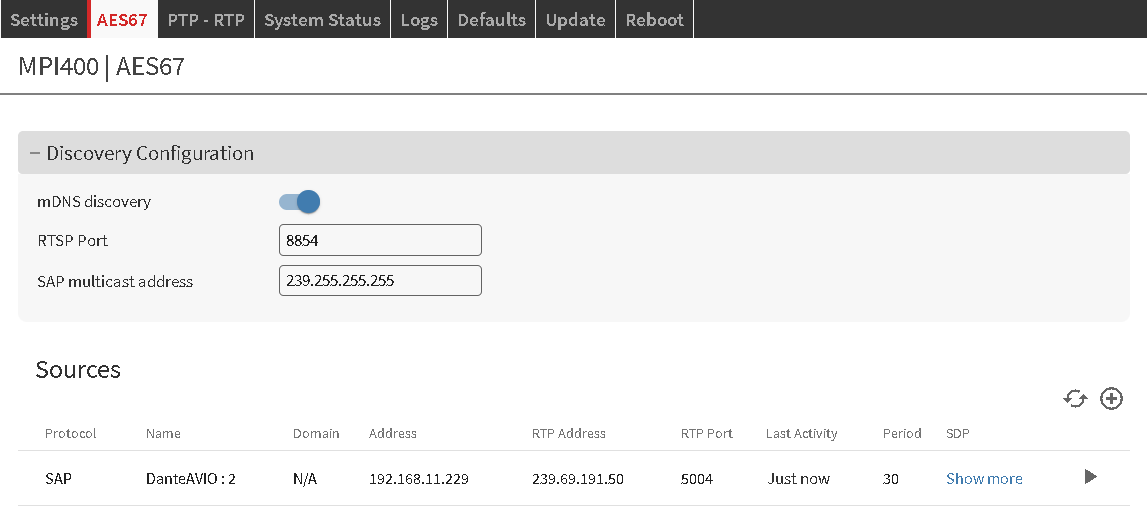
For more information on AES67 follow this practical guide, well done by Ravenna and published on The Broadcast Bridge.
AES67 Discovery
AES67 standard doesn’t specify any discovery mechanism. Discovery is the process of identification of AES67 streams in a network which also determines how the SDP (Session Description Protocol) file is exchanged in a system. The SDP file contains all relevant information about the RTP stream and can be used by the receiving device to setup its internal processes and play the stream accordingly.
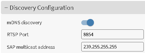
IPAC devices in AES67 mode support the following discovery methods:
mDNS: Multicast DNS using Avahi service. When this option is Active the application looks for services on the multicast group 224.0.0.251. The services advertised by third party devices (i.e. from RAVENNA) would allow further connection over RTSP (Real-Time Streaming Protocol) that takes care of the exchange of the SDP file. Default value: “Yes”
RTSP: Real-Time Streaming Protocol. It works in conjunction with mDNS (Avahi) and it is used to fetch the SDP file from the transmitter device, which runs an RTSP server. IPAC devices allow the possibility to set the port to be used for the communication to be established with the server (rtsp://<IPAC_IP>:[Port] - The [Port] can be configured in the Discovery configuration)
SAP: Session Announcement Protocol. This protocol sends at fixed intervals the SDP file containing the RTP description (stream description) to a well known multicast address. The multicast address to be used can be configured in the corresponding field. The interval is configured in the transmitting device (if available). Make sure that the IP Address used corresponds to the same multicast address used by the transmitter devices (the advertiser). The default value is set to use the SAP address used by Dante devices when are sending AES67 streams.
AES67 Sources
Here is where the streams (sources) found or manually added are listed.
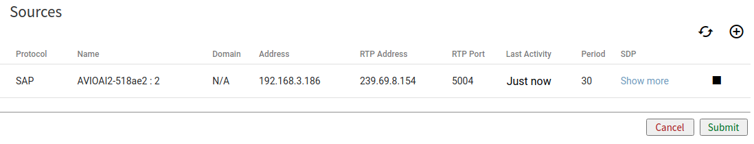
|
Protocol |
Informs about the discovery protocol used to identify the stream and fetch the SDP |
|
Name |
The name of the stream identified - For SAP / mDNS sources this name is the one found in the SDP file |
|
Domain |
This indicates which PTP domain is used to synch with this stream. AES67 PTP domain typically is always 0 when not indicated otherwise. This information is contained in the SDP file |
|
Address |
The IP Address of the TX device originating the stream. This information is contained in the SDP file |
|
RTP address |
The destination RTP Address used by the TX and from where the stream is retrieved. This information is contained in the SDP file |
|
RTP port |
The destination RTP port number used by the TX and from where the stream is retrieved. This information is contained in the SDP file |
|
Last activity |
Shows the last activity of this stream. When a stream is available this is “Just Now”. When a stream is inactive it shows the time since the stream became inactive NOTE: an inactive stream cannot be played and it can be removed from the list |
|
Period |
It is related to the SAP interval, how often the TX sends the SDP updates to the appointed multicast address. This information is automatically retrieved by SAP itself and advertised by the TX device |
|
SDP |
Allows to show the full SDP content provided by the TX device or if a source is manually added it shows the content of the SDP file provided 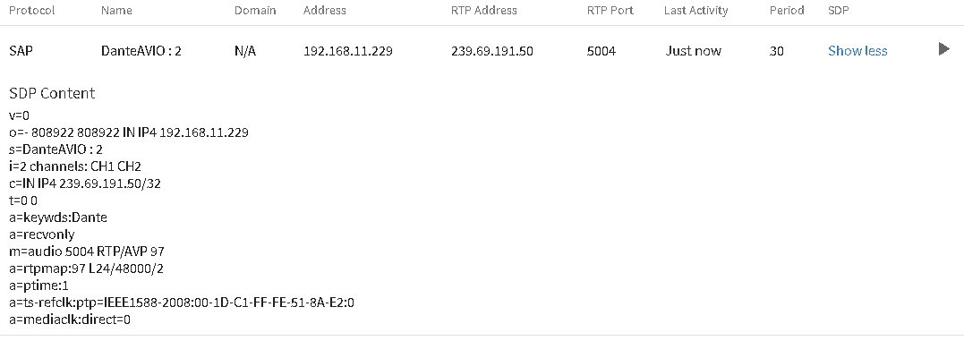
For all information about SDP Content click here |
|
Play/stop/remove |
PLAY: When a stream is found or manually added it can be played by clicking on the corresponding icon. The stream will play immediately. In case multiple streams are available only one at a time can be played. It plays always the last stream for which the PLAY button was pressed. STOP: When a stream is playing, it is possible to stop its playback at any time REMOVE: This button is available only when a stream is inactive. It allows to remove a stream from the list, but be aware that if the stream is advertised again by the TX via SAP or mDNS it will show up again |
|
Add a stream manually |
Click on the “+” icon on the top right corner of the list to add a stream manually providing the SDP content of the same - Some AES67 compatible devices doesn’t implement any discovery protocol but they provide an SDP file to be copied and pasted in the receiving device 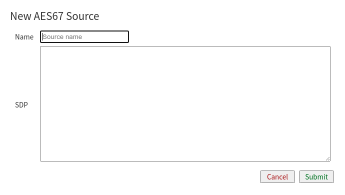
|
AES67 Supported Audio Format
The IPAC Implementation of AES67 implements the following audio format: L24/48000/2 (Linear PCM 24 bits / 48kHz sampling frequency / Stereo)
PTP - RTP
This page is an informative page with very important information on the PTP status and RTP statistics.
PTP or Precision Time Protocol is fundamental in an AES67 system as it is the backbone for the clock synchronization among different devices in the system. IP Audio Client can only act as a “follower” (or “slave”, term now deprecated in the industry), meaning that a Grandmaster clock device has to be present in the network to provide clock to IPAC nodes.
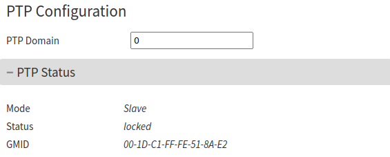
|
|
|
PTP Domain |
Set the PTP domain to be used. Domains allow multiple clock distribution systems to share the same communications medium. The Default domain for AES67 is 0, which enables devices to communicate via multicast address 224.0.1.129, where SYNC, ANNOUNCE, FOLLOW UP, DELAY_REQ, DELAY_RESP messages are sent by the devices in the system. Changing the domain changes the multicast address used. Default: 0 |
|
Mode |
This field can only be “slave” or “follower” as the current PTP implementation in IPAC devices cannot act as “master” or “leader” |
|
Status |
“locked” when the device is locked to the clock of the master device “unlocked” when the device is not locked to any master clock “locking” when the device found a master clock and it is synchronizing |
|
GMID |
Grand Master ID. The unique identifier of the device that has been elected as master clock provider |
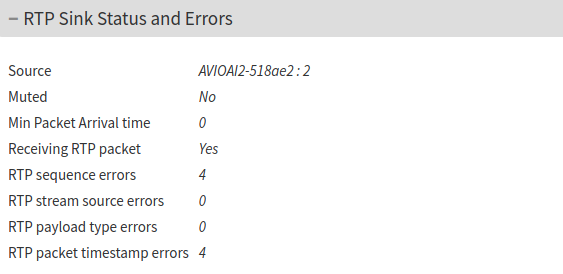
|
|
|
Source |
The name of the source sending RTP packets |
|
Muted |
Yes: when audio is not flowing to the output No: when audio is flowing to the output |
|
Min Packet Arrival Time |
Not implemented |
|
Receiving RTP packets |
Yes: when RTP packets are received by the tx No: when RTP packets are not received by the tx |
|
RTP Sequence errors |
Number of RTP sequence errors found at stream reception |
|
RTP Stream source errors |
Number of errors generated by the stream source |
|
RTP Payload type errors |
Number of errors due to a bad RTP payload type |
|
RTP Packet timestamp errors |
Number of packets with timestamp errors (normally increases along with the RTP sequence errors) |
Dante Application mode
Only available in Dante Licensed IPAC devices
This section describes the relevant functions present when the device is set to run in Dante Exclusive Mode.
In this mode the IPAC device doesn’t offer the multi-source arrangement with priority handling, the unit becomes solely capable of decoding 2 channels Dante streams.
Why Dante Exclusive Mode?
The end-to-end latency of a Dante source in IPAC Standard Mode takes into account the additional delay introduced by the multi-layered architecture and is approximately 190 ms. For customers deploying devices in Dante-only systems where no other sources are needed, it is possible to use this mode that achieves an end-to-end latency of 8 ms (measured with a Dante AVIO 2x0 set to encode at 1 ms delay).
There is no Dante related control available in Dante Exclusive Mode. All the controls and configuration is performed in the Dante Controller.
From the IPAC web configuration interface it is still possible to access the SETTINGS, DANTE STATUS, LOGS, UPDATE, REBBOT and UPDATE tabs, well described throughout the previous chapters of this manual.
Dante Exclusive Mode - Quick Start
When using the IPAC device in Dante Exclusive Mode follow these steps to get your unit up and playing a Dante stream in seconds.
|
1 |
Connect the IPAC device and power up. The unit takes between 40 to 50s to boot. |
|
2 |
Open Dante Controller from a PC in the same network of the IPAC device. |
|
3 |
In the routing table of Dante Controller make the necessary connections to play audio from a Dante transmitter |
|
4 |
In case a multicast stream is required (when routing audio to 2 or more IPAC devices), enable multicast flow in Dante controller for the transmitter device used. |
Compliance and further Information
This equipment has been tested and found to comply with the limits for a Class B digital device, pursuant to part 15 of the FCC Rules. These limits are designed to provide reasonable protection against harmful interference in a residential installation. This equipment generates, uses and can radiate radio frequency energy and, if not installed and used in accordance with the instructions, may cause harmful interference to radio communications. However, there is no guarantee that interference will not occur in a particular installation. If this equipment does cause harmful interference to radio or television reception, which can be determined by turning the equipment off and on, the user is encouraged to try to correct the interference by one or more of the following measures:
-
Reorient or relocate the receiving antenna.
-
Increase the separation between the equipment and receiver.
-
Connect the device into an outlet on a circuit different from that to which the receiver is connected.
-
Consult the dealer or an experienced radio/TV technician for help.
Safety and precaution recommendations apply. Find them in the download section at www.barix.com

Find your distributor on this list for more hardware.
For questions that are extending the documentation, feel free to contact us on:
International: +41 434 33 22 22
USA: +1 866 815 0866
Email: support@barix.com
All information and the use of this product including all services are covered under the Barix Terms & Conditions and our Privacy Policy. Please follow the Safety and Precaution Recommendations. Barix is a ISO 9001:2015 certified company. All rights reserved. All information is subject to change without notice. All mentioned trademarks belong to their respective owners and are used for reference only.