LX400 STL User Manual
Introduction
The aim of this document is to guide the user through the functionalities of the STL application, which is the software running on the following Barix Products:
PN | Description | |
2024.9439P | LX400 STL Package |
The STL Application is running on the top of the “Flexa” firmware; this applications can only run on top of these “Flexa” devices. It is not possible to install the “Flexa” firmware on any other device and it is not possible to convert any other device into a “Flexa” one.
About this manual
This manual is intended for distributors, installers and end users of the LX400 STL. It will cover first configuration steps plus details on how to use the application after installation.
This manual describes the functionality of the latest Flexa firmware version and latest overlaying STL application.
Barix always recommends to run the latest software available on the device and provides a dedicated download area for registered users on https://help.barix.com .
Additional documents and support
The following additional documents are available for LX400 STL:
Quick Install Guide, https://help.barix.com/lx400-stl/lx400-stl-quick-install-guide
LX400 STL - Knowledge Base articles
Product sheets: these documents are available for download on the Barix website for all users in the download area http://www.barix.com/downloads
Beside checking regularly the Barix website and the Barix help, the user has access to support in several ways:
check with your local distributor for the technical support they offer; a list of distributors is also available on the Barix website at this link;
email directly a Barix support technicians at support@barix.com.
What is LX400 STL?
LX400 STL is a codec for Studio Transmitter Link (STL) application.
Key features include support for MP3, OPUS, AAC, AAC+ and PCM uncompressed audio coding, absolute end-to-end delay control (RTP), latest security (HTTPS) and stream redundancy modes for uninterrupted broadcasting. Additionally, it offers 8 I/O contacts and AES3 compatibility on StudioHub connector (output only). Two power options (redundancy) via 24 VDC and PoE are supported. The audio streaming is uni-directional from one LX400-STL encoder to one or many
LX400-STL decoders; the data communication is bi-directional (see BRTP description below).
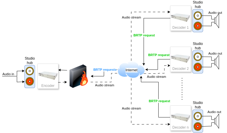
Use case
An example use case is presented below.
General Features
Encoder or decoder settable
Protocols: RTP (BRTP)
OPUS, AAC, AAC+, MP3, PCM audio codecs
Stream redundancy
Decoders synchronization
Constant system delay
Backup URL (decoder - HTTP/HTTPS)
Backup audio files on USB stick (decoder - MP3)
Balanced Stereo Audio input and output on StudioHub RJ45 connector
AES3 Digital Audio output on StudioHub RJ45 connector
RS232 and TCP gateway (metadata)
Contacts gateway
UDP commands for relays control
HTTP/HTTPS web UI
Power redundancy: 24 VDC and PoE
Barix RTP (BRTP)
The Barix RTP (BRTP) protocol was designed by Barix AG as a simple extension to the RTP protocol to support the following:
allow a client to register at a server to subscribe to a RTP stream;
detect client dropout quickly and reliably to prevent loading of the network with a stream that is actually not consumed;
provide a keyword-based access;
penetrate routers and firewalls employing Network Address Translation (NAT).
BRTP is RTP with subscription request packets added.
The subscription request packet is an UDP datagram which contains only a keyword; if the receiver requires no access control then any UDP packet suffices.
The subscription request packets are sent periodically by the client to the server.
The RTP stream is sent to the return address of the BRTP packets; if subscription is not renewed within 30 seconds, then the client is removed from the target table for the RTP stream.
The BRTP packet on it’s way out penetrates a NAT (for NATs where it is possible) and opens a back channel for the RTP; this way RTP can be received even on clients which don’t have public IP addresses.
Constant audio delay across all devices
The user is able to configure constant audio delay from the moment of audio processing on the encoder device until the moment of the playback on the decoder devices. This delay will be kept across the whole setup where physically possible.
Profanity zapper compatible
In case a profanity zapper is used, the operator can configure a delay (Contacts Closure delay) on
the encoder device, which reflects the delay introduced by the zapper. This way the constant
audio delay is kept across the whole setup.
Stream stability
Improved stream stability can be used by Redundancy.
If the network is not stable and there are packet losses, the user has the ability to activate the Redundancy on the encoder.
This will force the encoder to send the encoded audio data second time with a short delay
after the original stream. The decoder devices will then be able to replace any missing packets
from either of the streams, and put them together.
Backup stream
If desired, the user has the ability to provide an HTTP stream URL to be used as a backup
audio source.
In case there are some issues with the encoder of the main stream and there is no audio data arriving on the decoder, the backup stream will automatically start playing, until the main stream recovers.
To ensure good listening experience, there is also a configuration of the minimum time the backup stream should play, before the decoder tries to go back to the main stream; this way the so called "ping-pong" between the two streams can be avoided.
Backup USB playlist
Connecting an USB stick on the decoder with MP3 audio files inside, it’s possible to have a further source as audio backup. It has lower priority than the backup stream.
So, if you want to use it, then you should either not configure a backup stream, or have it but not working. Then when the main stream drops, the USB playback should start automatically after a short silence period.
Relay control
The user is able to send relay control commands synchronized with the audio stream.
This can be done in one of two ways - by using the UDP command server running on the
Barix LX400 encoder device, or by using the contacts gateway.
Contacts gateway
Whenever needed the user can close one of the 8 inputs of the Barix LX400 encoder device.
Doing so it will send a command to all connected decoders to switch the corresponding relay
on their side, synchronous with the audio at the time of closing the input.
Large setup with a single encoder
The Barix LX400 encoder can distribute the encoded audio to up to 72 different Barix LX400 decoders.
Metadata transmission
The user is able to encode metadata in the stream, as well as receive it at the time of playback. This can be done either by using the TCP servers on both encoder and decoder devices, or by using the RS232 serial interface on the devices.
Before you start using the LX400 STL
A few things you need to know before you can effectively use the LX400 STL broadcast encoder decoder.
What is FLEXA
The LX400 STL runs a firmware that is called FLEXA. STL is an application running on the FLEXA firmware. That should not concern you. Most important for you are the menus SETTINGS, CLIENT HOME and LOCAL CONFIG.

No need to press any of the buttons on the HOME screen. Key there is that it shows “Application Status running”.
When you enable the FLEXA AGENT, then the unit will call into the Internet (if it can reach it) and automatically get firmware updates. It also enable Portal Config via SUPICONF (see below).
To run the unit stand-alone with the local GUI for configurations, disable the FLEXA AGENT.
Important: If you have the FLEXA AGENT enabled, and then try to change the configuration you will get the following warning.
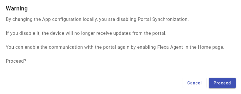
If you click "Proceed", then the FLEXA agent will be disabled, putting you back in stand-alone mode.
What is SUPICONF?
Your LX400 STL is SUPICONF ready. SUPICONF is a future Cloud portal solution by BARIX that allows you to configure the unit via a Web Portal instead of locally via Web GUI.
The Portal is available in Beta version and you can try it.
A key shortcomings of the Beta Version is that synchronization between the Portal and the device only happens once an hour. This will be improved to a much shorter reaction time in the final release.
Interested in SUPICONF?
If you are interested in SUPICONF and want to get an account, please contact the vendor who sold you the unit. They can enable your free SUPICONF account.
Package Content
LX400 device
Quick Install Guide
The LX400 STL is an audio over IP encoder with analog audio I/O and AES output on StudioHub (RJ45) connectors.
See here about StudioHub: https://studiohub.com.
Installation
STEP 1 Connect the Audio Equipment
The LX400 STL provides balanced line level analog audio I/O and AES output on StudioHub (RJ45) connectors, to be connected to a mixer, an FM modulator/transmitter, an amplifier, etc.
You can listen the IP address of the device directly after reboot played on the analog audio output (https://help.barix.com/knowledgebase/what-is-sonicip ).
STEP 2 Connect the network
Connect your LX400 STL to the network using a standard Ethernet cable (CAT5e or better) through the port labeled POE.
If you’ve a PoE switch or a PoE injector (802.3af compliant) you don’t need to use an external power supply.
STEP 3 Boot the device
After to have connected the Ethernet cable to a PoE device or to have plugged in the power supply, the device will boot:
Right after power-up left status LED is red (boot in process)
5s after power-up → left status LED starts blinking and right status LED is solid red
about 15s after power-up → Device announces its IP Address over the analog and digital audio output (take note to be able to enter the web interface later) → Left LED turns from red to green
about 30s after power up → Application is ready → both status LEDs are solid green
LX400 STL is ready to be configured.
Note:
You can connect PoE as well as an external power supply at the same time. The equipment will use the power sources as redundant sources without the need for interaction.
First Configuration
| 1 | From a PC in the same network subnet of the device, use a web browser to access the web interface by typing the IP Address into your browser. There are two ways to find the IP address of the unit:
|
| 2 | Login is required, by default user is "admin" and the password is provided on the sticker on the backside of the device (PW label). 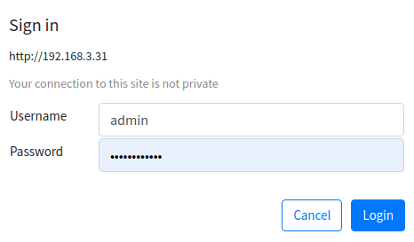 |
| 3 | On the “Home” page you get information about the application status. |
| 4 | 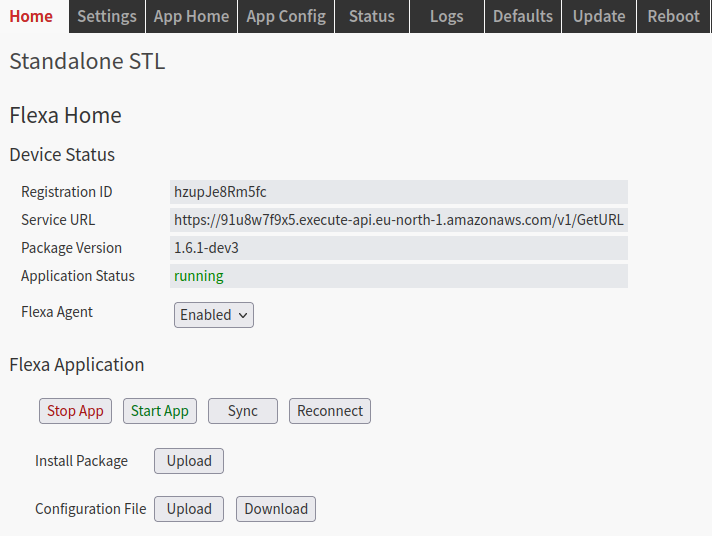 Go to the “Local Config” where you can configure the STL application settings. First of all configure the Device type (Encoder or Decoder). 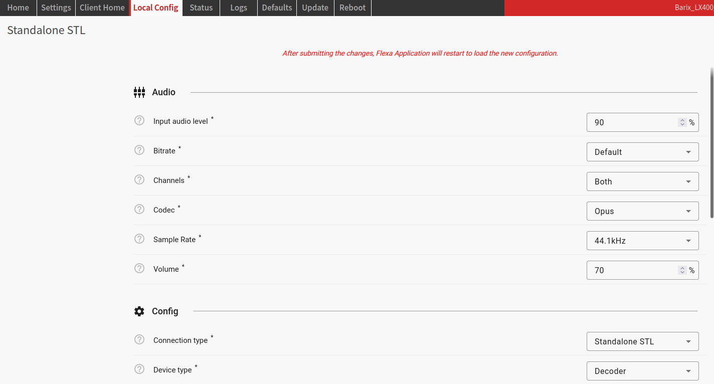 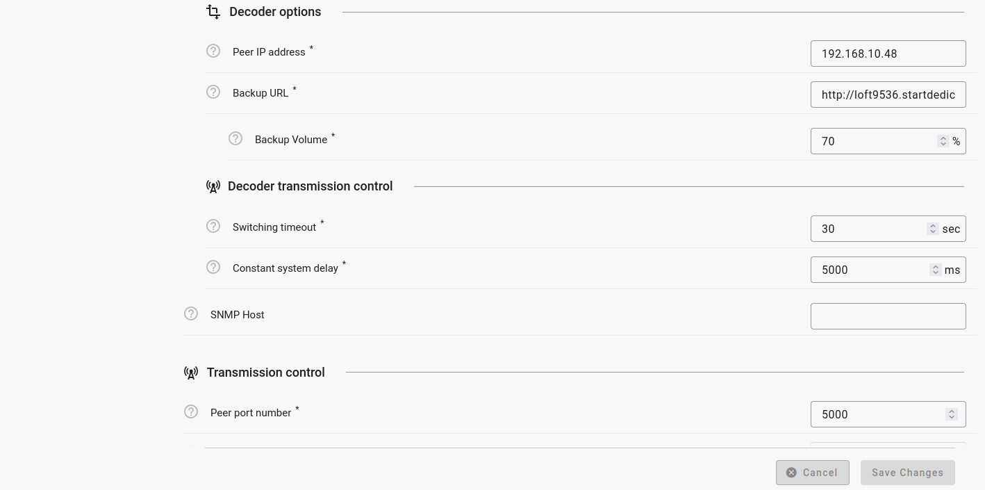
|
| 5 | When done, click “Save Changes ”. Important: If you have the FLEXA AGENT enabled, and then try to change the configuration you will get the warning below. |
Hardware functionality
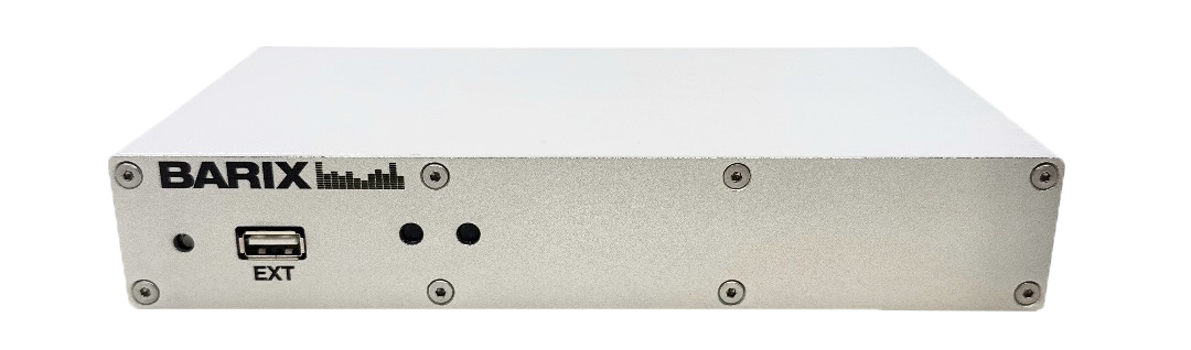
Front View
| Rear View
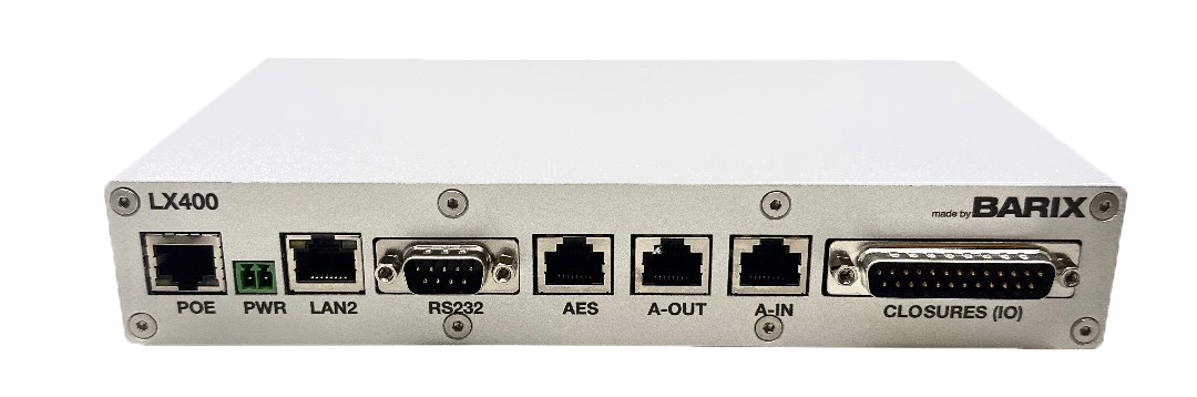
| ||
RESET button | Short press while powered (1s - 9s) → Reboots the device Long press while powered (10s - 19s) → Hard reset to defaults (including network settings) Press and hold for 30s while powering up → Rescue process triggered: device will connect to the Barix update server and install the latest firmware | POE (Ethernet 10/100 ) | Fast Ethernet network connection on RJ45 and PoE (802.3af) |
EXT Port | To connect external USB devices, | PWR (Power) | Power connector (terminal block) |
LEDs (see tables below) | As per picture above:
| LAN2 | Not supported at the moment |
|
| RS232 (115200, N, 8, 1) | Metadata I/O DB9 connector. Pinout:
|
|
| AES (Digital Audio Output) | StudioHub RJ45 connector. Pinout available according to Studiohub standard. |
|
| A-IN (Analog Audio Input) | StudioHub RJ45 connector. Pinout available according to Studiohub standard.
|
|
| A-OUT (Analog Audio Output) | StudioHub RJ45 connector.Pinout available according to Studiohub standard.
|
|
| GPIO (see image below) | Input contacts and relay outputs. D-SUB 25 pin (male). Connection Pinout:
|
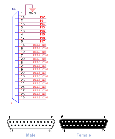
D-SUB 25 pinout (male)
LED indications
State | Left led | Right led |
|---|---|---|
Booting | flashing red | solid red |
Flexa firmware running | solid green | |
STL application running | solid green | solid green |
STL application stopped | solid green | solid red |
State | Encoder right led | Decoder right led |
|---|---|---|
Streaming | solid green | solid green |
Decoder off | flashing red | |
Encoder off (backup on decoder) | flashing green | |
Encoder off (no backup on decoder) | solid red |
Getting IP address from the device
In this chapter are detailed all the methods that can be used to retrieve IP Address of the LX400 STL.
Retrieve the IP address using the Sonic IP® function
All Barix audio devices are equipped with a function called “Sonic IP®”, meaning that when you boot the device and this is connected to a network where a DHCP server is present, the device will acquire an IP address and announce it over its audio output. This function is useful when you connect to the device for the first time and need to access its web interface for performing the first configuration. The LX400 STL is playing out the IP address directly after reboot on the analog StudioHub output.
Follow the below steps to take advantage of the SonicIP function:
Connect the audio output to the receiving system;
Make sure the receiving system works fine so that when the Barix device boots you are able to hear the IP Address;
Power up the device,
After 20 secs listen to the Sonic IP® announced and note it somewhere;
After 35 secs the device is ready.
Retrieve the IP address using the Discovery Tool
Other than the Sonic IP® function, there are other ways to find out a Barix device’s IP address. One is by using the Discovery Tool from Barix.
The Discovery Tool is freely available for download from https://help.barix.com/tools/discovery-tool.
The Discovery Tool is written in the Java programming language, so it requires a Java Runtime Environment (JRE) installed on your computer. If you do not have a JRE installed, you can download and install it from https://www.java.com/en/download/.
Java run time environments are available for many major operating systems. If you are running the Discovery Tool on a Linux or UNIX platform, the Discovery Tool also requires the X-window graphical user interface.
The Discovery Tool is distributed in a Java Archive (.jar) file. On most operating systems you can run the Discovery Tool by simply double-clicking on the discover.jar file.
Click the "Get" button to initiate a search. The program will scan the local network and lists all the Barix devices found with its current IP address, MAC address (labeled "Ethernet Address"), firmware version, and other information. On the picture below you can see how it looks when a LX400 STL is found.
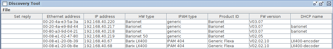
The Discovery Tool will find all Barix devices that are on the same network as the computer running the tool, regardless of their current IP address setting. The tool will not search through a router to another subnet. Use the address that appears in the Discovery Tool to access the Barix device via a web browser.
Setting a static IP Address using the Discovery Tool
In the discovery tool window, double click the IP Address field of the device which you want to change and set the static IP address.
Enter the IP address you want to assign.
Click SET in the lower right corner - the tool will reply with a “No error” in the “Set reply” column.
Reboot your device and access the web interface through the newly assigned IP address. Make sure to finalize the network settings configuration (Subnet, Gateway, DNS), otherwise the device might not work correctly.
If the Barix discovery tool is not discovering Barix devices in the local network, then make sure you have not opened the Discovery tool twice on the same PC or any PC firewall is blocking the traffic.
Homepage
When you browse the IP address of the LX400 STL and you have logged, then you will see the homepage on your browser. On the homepage of the LX400 STL there are device information available.
The window is organized in:
The top navigation bar; in addition on the top right corner there are the MAC address and current firmware installed on the device
The information area, where the user can see the application status.
The help section on the right side of the window/page.
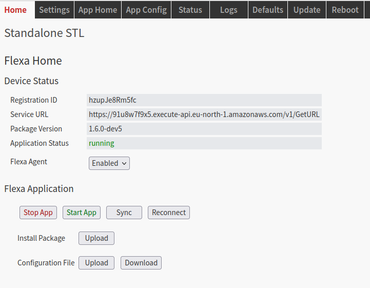
Device Status
The Registration ID and Service URL are information the device needs to contact the SUPICONF Cloud portal.
Package Version is the current LX400 STL application version and the Application Status shows you the application currently running or stopped. If stopped then the device will not stream/play and the other settings are probably not available.
Flexa Agent is the task that take care of the communication with Barix Cloud portal (enabled by default).
Flexa Application
Usually all these buttons are not needed under normal circumstances.
The buttons Start App/Stop App allow to start/stop the LX400 STL application manually.
The Sync button and the Reconnect button forces the device to connect to the SUPICONF Cloud portal, but for that the device must be registered on the SUPICONF Cloud portal.
Install Package and Configuration File are currently not supported functions on the LX400
Settings
Under Settings you can configure device specific settings.
Here you can find the sub menus for the Audio Settings, Network Settings, the Time Settings and the Security Settings.
Also here you can find an online help on the right side of the page.
Click on the desired button to open the according menu. Make your changes and finally scroll down and click “Submit” to save the changes and make the changes active.
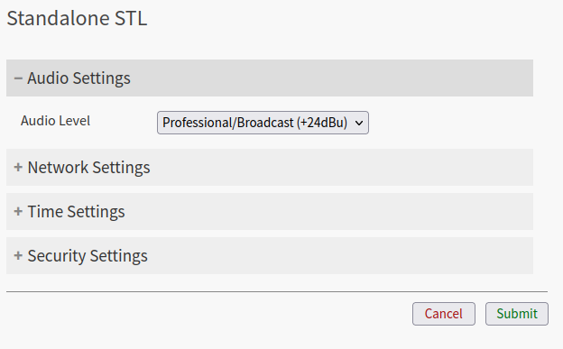
Audio Settings
Audio Level
Select the level of the audio output - broadcast or consumer.
They are applied without restarting the application.
Note: Selecting the wrong level can cause clipping of the output sound.
Default: "Professional/Broadcast".
Network Settings
In this area, it is possible to configure the device’s network settings and few other functions.
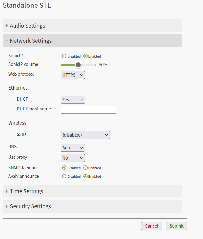
Per default setting the STL LX400 supports the Dynamic Host Configuration Protocol (DHCP), which allows the device to acquire an IP address available from a pool of addresses hosted by a DHCP server. It is the server that offers an IP address to the device when discovered on the network. The IP address offered by a DHCP server comes with a lease time, meaning that when the leased time is over the DHCP server re-issues the IP addresses to the devices on the network, with the possibility that it might assign a different address than the one assigned previously. In addition, the DHCP server provides all associated information to the requesting device, such as subnet, gateway, and DNS addresses.
Item | Available values | Description |
|---|---|---|
Sonic IP / Sonic IP Volume | Enable , Disable | Enable / Disable the Sonic IP function so the device announces its IP Address directly after the boot process. Default: Enable Set the volume of the SonicIP with the corresponding slide. Default: 50% |
Web Protocol | HTTP, HTTPS | Configure the protocol used to access the web interface of LX400. It can be HTTP or HTTPS. When set in HTTPS the communication between the browser and the device is encrypted. The application uses a self-signed certificate for the SSL/TLS authentication, not one from a CA (Certificate Authority) considered safe from web browsers. For this reason when using HTTPS the browser will warn that the certificate used is not a trusted one (NET::ERR_CERT_AUTHORITY_INVALID). To continue and open the web interface it is necessary to advance manually, “forcing” the browser to trust the self signed certificate. The connection and data communication will be fully encrypted. Default: HTTP |
DHCP | Yes, No | Set the DHCP (Yes) or Static IP addressing mode (No). Default: DHCP |
DHCP host name Only available with DHCP enabled | Provides the DHCP with an host name to easily identify the device in the DHCP list of leased IP addresses. Default: " " | |
IP Address Only available when DHCP disabled Netmask Gateway IP Address | Configure here the static IP address for the LX400 when DHCP is disabled. The IP address is the unique identifier of a device on a network, in case of static assignment make sure that no other device on the same network has the same IP address assigned to the LX400. | |
In addition to the IP address, it is mandatory to provide information about the subnet mask. The subnet mask indicates which bits in the IP address are used for the network portion and which bits for the host portion. It is common in Class C LAN to see 255.255.255.0; this configuration indicates that the first 3 octets of the IP address (e.g. 192.168.0.100) are dedicated to the network identification, while the last octet (e.g. 192.168.0.100) is dedicated to the host identification on the network. | ||
The Gateway IP is the address of the device that bridges your Local Area Network with other networks or the Internet. Typically is a router where devices on a LAN are connected. For using the LX400 in all its cloud-based features, but also to receive a stream from an Internet radio in stand-alone mode, for example, it is essential to provide this address. If you are not sure about the Gateway address in your network contact your network administrator. | ||
DNS | Auto , Manual | Set here whether you will use the DNS settings from the DHCP server (Auto) or you will use set your own DNS settings (Manual). Default: Manual |
Use Proxy Only available when Proxy enabled Host Port User Name User Password Exceptions | Yes, No | Enable/disable proxy settings. If your network uses a proxy server then you have to enable this function. Default: No If set to “Yes” you can configure the following settings: Set here the proxy server hostname/IP address. Define here the proxy server port. Configure the proxy user name. Configure the proxy user password. List here the Proxy exception as a list of comma separated entries. If empty, mean no exceptions. Allowed format for entries
|
SNMP daemon | Disable, Enable | Enables/disables SNMP protocol Default: Disable |
Avahi Announce | Disable, Enable | Enable/disable Avahi Announcement Default: Enable |
Time Settings
The STL LX400 uses an NTP daemon to set its system time, this time e.g. used in the internal LOG files. The NTP protocol uses the standard port 123.
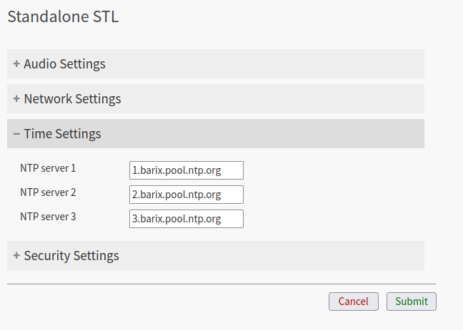
Here you can configure the IP address or DNS address of the NTP servers.
Default:
1.barix.pool.ntp.org
2.barix.pool.ntp.org
3.barix.pool.ntp.org
By leaving the configuration fields empty it is possible to disable the NTP function.
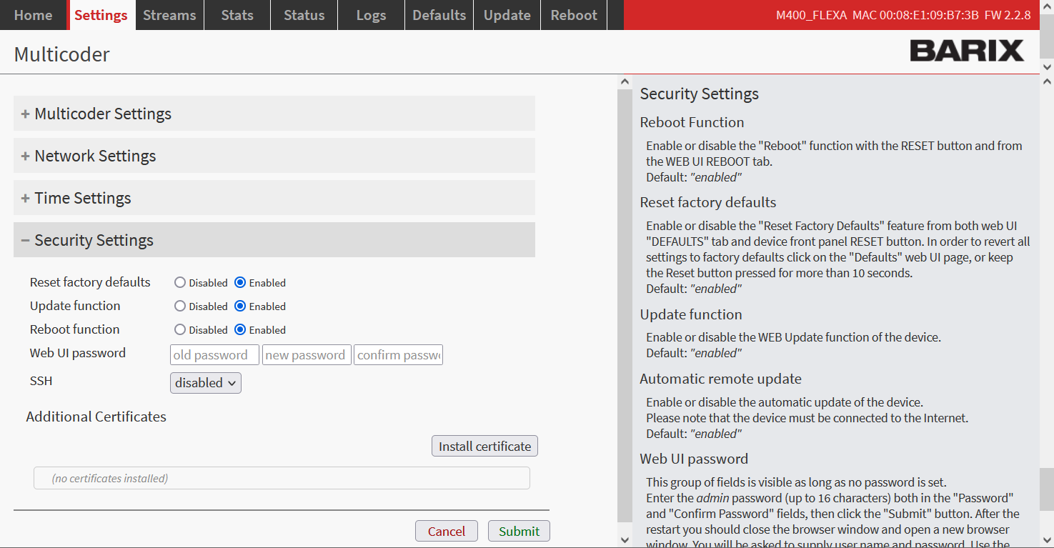
Security Settings
This area is dedicated to secure the login to the device web interface and to enable or disable the possibility to run critical operations: reboot, reset to factory defaults and update
Security Settings
Item | Available values | Description |
|---|---|---|
Reset Factory Defaults | Disable, Enable | Enable or disable the possibility to reset the device to factory default from the web UI. Default: Enabled |
Update Function | Disable, Enable | Enable or disable the possibility to update the device from the web UI. Default: Enabled |
Reboot Function | Disable, Enable | Enable or disable the reboot function of the device from the web UI. Default: Enabled |
Web UI Password | Set the password to access the web interface of the device. If a password is already set another field is displayed: OLD PASSWORD, which is required to modify the current password. When you set a new password then you have to enter it twice for confirmation. Default password: printed on the backside of the device The default user name is “admin” and cannot be changed. | |
SSH Access | Disable, Enable | Enable or disable SSH service. Only enable SSH Access upon request of Barix support, otherwise leave the option disabled. Default: Disabled |
Additional Certificates | Allows the possibility to upload custom .crt certificates to the device. Useful when the device is used in private enterprise networks where a private CA is in place to validate secure connections. Default: None |
Note: it is recommended to change the password when you connect the first time to the device.
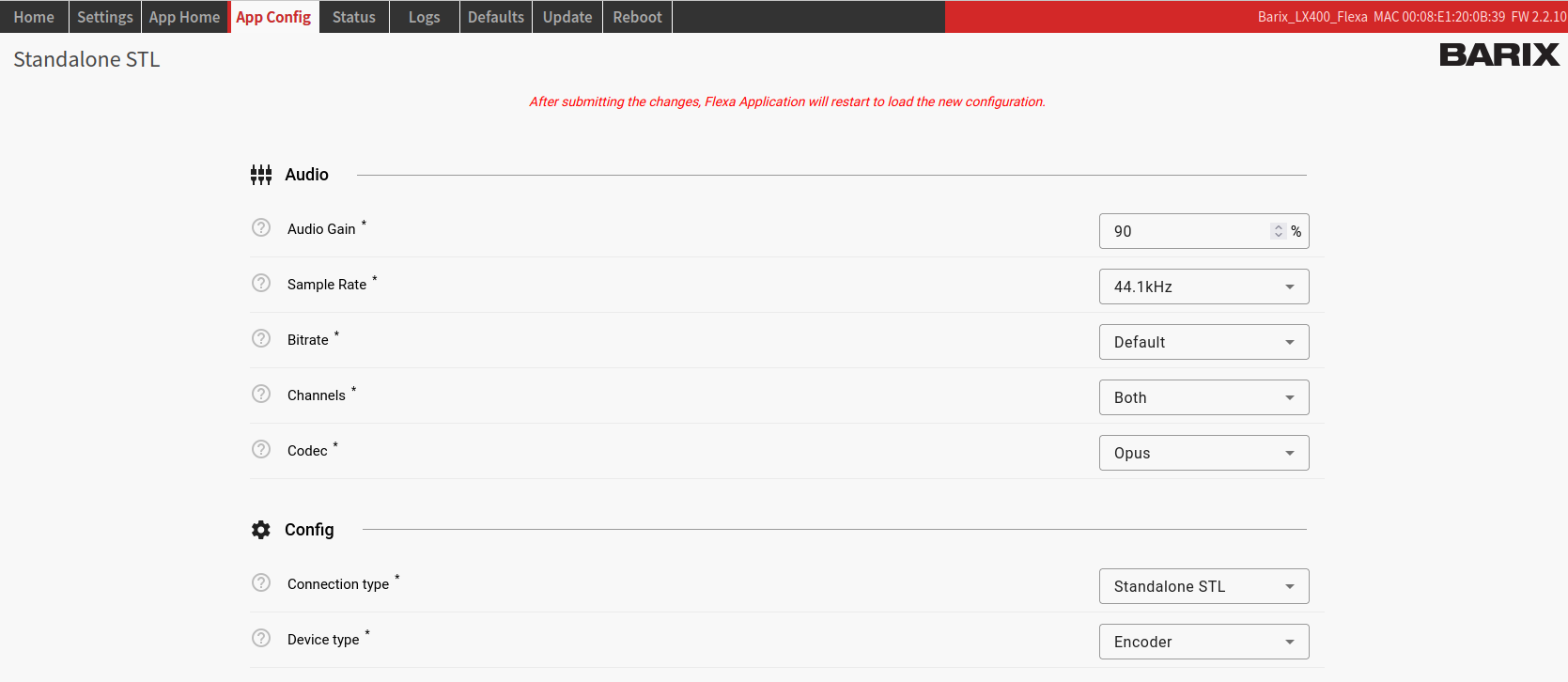
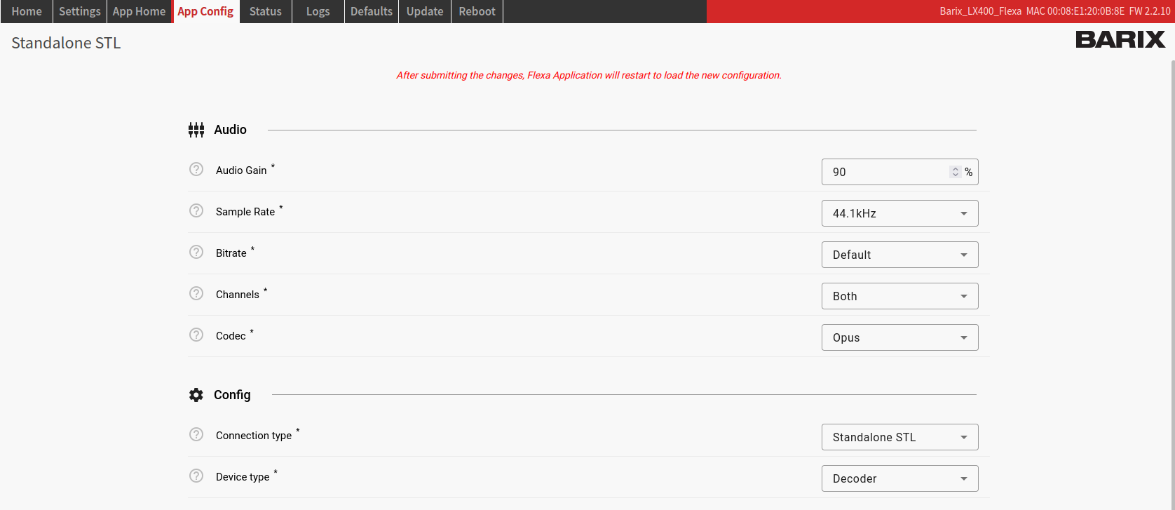
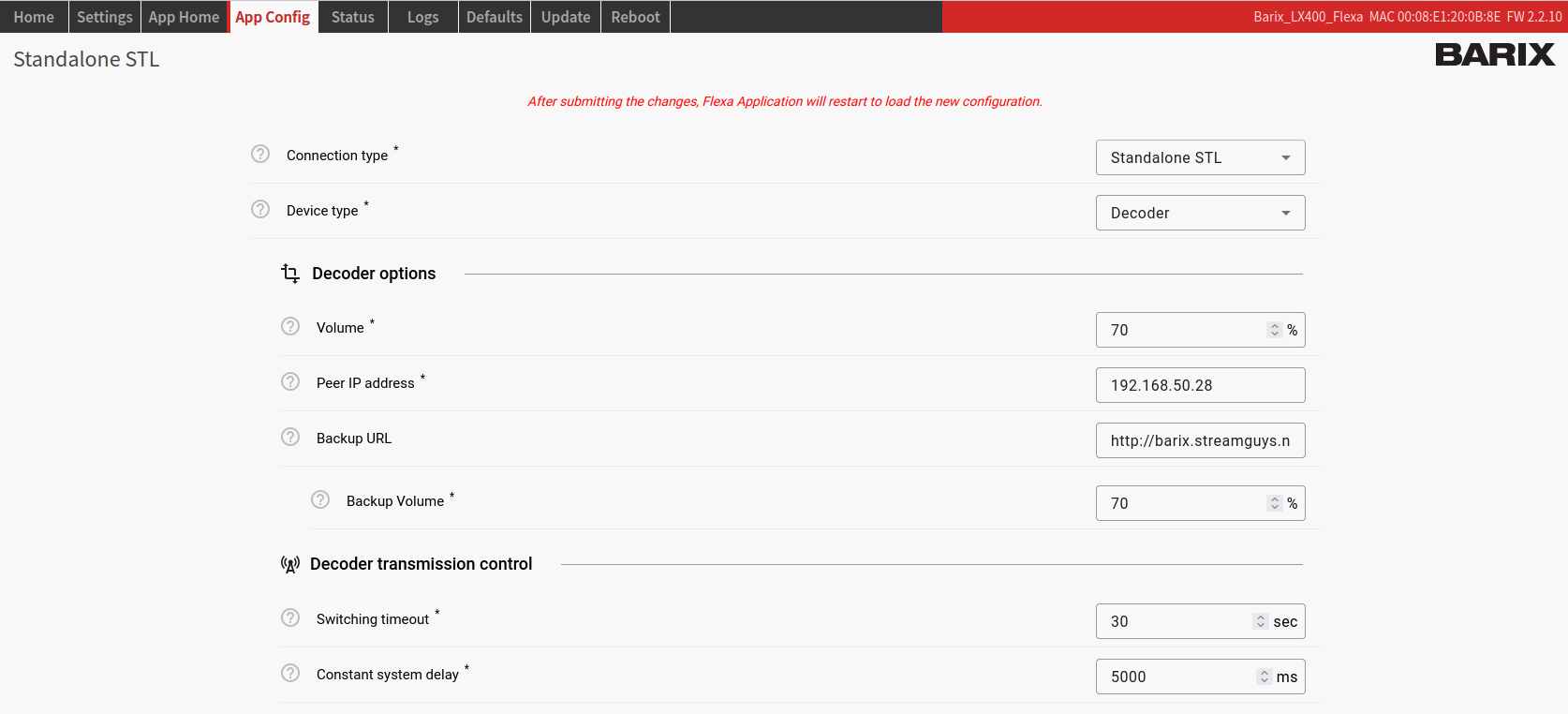
App Config
On the App Config page you can set all the parameters of STL application.
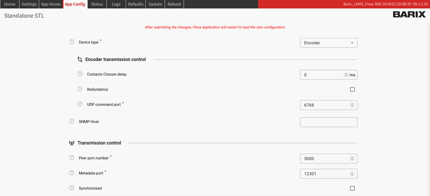
Item | Available values | Description |
|---|---|---|
Audio Gain | 0-100% | Input audio gain for an encoder device, output audio gain for a decoder device. Default: “90%” |
Sample Rate | 32, 44.1, 48 kHz | Sampling rate used for the stream. Default: “44.1 kHz” |
Bitrate | 32, 48, 64, 96, 112, 128, 160, 192, 320 kbps | Bitrate of the audio stream. |
Channels | Left, right, both | Audio channels to be used for the audio. Default: “Both” |
Codec | AAC, AAC+, MP3, OPUS, PCM | Audio codec used for the stream. The selection must be the same on the encoder and the decoder devices connected to it. Default: “Opus” |
Device Type | Encoder, Decoder | Set device to act as Encoder or Decoder. Default: “Decoder” |
Contacts Closure delay | 0-30000 ms | Encoder only. Delay to add on the relay closure (e.g. to sync with audio). Default: “0” |
Redundancy | Enable, disabled | Encoder only. If the network is not stable and there are packet losses, the user has the ability to activate the Redundancy on the encoder. |
UDP command port | 6760-6770 | Encoder only. The port number to be used, on which UDP control commands will be received. Those commands are used for relay controls Default: "6768" |
Volume | 0-100% | This is used both for the main audio stream as well as the backup streams. For the backup stream it serves as the maximum possible value, but can be then further adjusted with the backup volume settings. Default: "70%" |
Peer IP address | The IP address of the respective server (encoder). | |
Backup URL | URL of an HTPP online stream, which will be used in case the main stream is not available. | |
Backup volume | 0-100% | Backup URL volume. Default: "70%" |
Switching timeout | 0-240 sec | Decoder only. Timeout (absence of main stream) to switch to Backup URL. Default: "70%" |
Constant system delay | 3000-25000 msec | Decoder only. The desired audio transmission delay from the time of encoding until the time of playout. Default: "3000" |
SNMP Host | IP address of the host SNMP device, where traps will be sent to. | |
Peer port number | 1025-65535 | For an encoder device this is the BRTP listen port to use; for a decoder, this is the BRTP server port number to connect to. Default: "5000" |
Metadata port | 12300-12400 | The TCP port number on which the Default: "12301" |
Synchronized | Enable, disabled | Decoder only. Normally all devices will be NTP synchronised. In case there are issues with NTP, this can be disabled to improve the transmission reliability. However, this deteriorates the constant delay of the transmitted audio. Default: "enabled" |
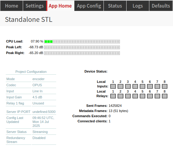
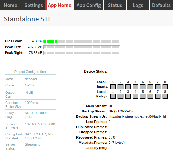
App Home
The Client Home tab is application specific tab; here all the information is relevant for
the currently STL running application.
On the left side of the page there are three distinctive sections with information: CPU
load and audio levels, the current device configuration and the device status.
The Project Configuration section includes some of the configurations of the device.
Here you can also see when was the last configuration change and whether the server is up.
The Device status includes information about the Local Inputs and the Local Relays of
the device; when a relay is activated or an input is close, the corresponding number will
light up.
There is also information about the main stream, back-up stream and packet transmission; it can help the user detect potential issues on the network or the stream.
See the side Help panel for more info.
Encoder
Decoder
Stream Metadata
The Standalone STL clients have the possibility of transmitting and sending metadata
encoded with the stream. This is done by using a TCP server running on the Barix LX400
devices, on the configured Metadata port.
Encoding metadata is very easy. On Linux you can directly use telnet utility. For Mac/Windows
there are equivalent alternatives.
Connecting to the metadata TCP server on an Encoder device, the user should see the
following:
$ telnet 192.168.1.1 11111
Trying 192.168.1.1...
Connected to 192.168.1.1.
Escape character is ’^]’.
Please provide metadata:
From this point on, anything that is written in the terminal will be synchronously
encoded with the audio data, and sent over the audio stream to the decoders. Once sent, a
timestamp of sending will be also displayed on the same terminal window. Note that this
timestamp is for user informational purpose only, and it is not sent together with the audio
stream.
Here is an example of sending metadata:
Please provide metadata:
This is an example for metadata encoding
[15:19:43 UTC, Thu 06 Feb 2025] Metadata sent!
Once finished, the user can close the telnet session. The Barix LX400 device will
automatically disconnect the TCP client.
Decoding metadata is just as easy. Once connected to the TCP metadata server on a
Decoder device, the user should see the following:
$ telnet 192.168.1.2 11111
Trying 192.168.1.2...
Connected to 192.168.10.183.
Escape character is ’^]’.
Incoming metadata will be provided here
When new metadata is received, it will be also displayed in the terminal, where the TCP
session has been established:
Incoming metadata will be provided here
This is an example for metadata encoding
As you can notice, in this example we see the same metadata that has been sent from
the encoder, but without the timestamp as expected.
The decoded metadata is displayed synchronously with the audio at the time of encoding.
The metadata (and audio) latency are affected by the selected value of the Constant delay
configured. E.g. if there has been 5 sec constant delay configured, that would mean that
the metadata sent will be displayed on the Decoder device 5 seconds after it was sent.
It’s also possible to use the RS232 serial interface to send metadata from the Encoder to the Decoder (RS232 parameters 115200, N, 8, 1).
Relays Control
To control the relays of a device the user can use simple UDP commands. Relay control commands are only processed when received on an encoder device. decoder devices do not process incoming commands on the UDP server port.
Here is the format of the commands:
BABROAD,SETIO,,2000.
Where:
Component | Values | Description |
|---|---|---|
Magic word | BABROAD | "Magic" word at the start of each new command. |
Command | SETIO, SETIO_LOCAL (on encoder only) | Different available commands to execute. |
Relay N | 1-8, * | Number of the relay to be controlled. * stands for all |
Delay | 0-1; 100-30000 ms | Value to be set to the selected GPIOs. 0 for OFF, 1 for ON. |
End of command | . | Each command must end with a . |
On Linux, in order to use this, the user can use the following command in the terminal:
echo -n "BABROAD,SETIO,*,2000." | nc -u 192.168.1.1 6768
Which is sent to the Encoder device of the setup, and will instruct all Decoders to switch
on all of their relays for 2000 ms.
Similar command can be constructed in order to control the Encoder device relays:
echo -n "BABROAD,SETIO_LOCAL,*,2000." | nc -u 192.168.1.1 6768
Reset to factory defaults – Hard reset
It is also possible to perform a hard reset. A hard reset will revert all settings to factory defaults including the network settings.
To perform a hard reset locate the reset button on the front panel of the LX400 device and keep it pressed for approximately 11 seconds using a sharp-pointed tool while the device is running. The status led will blink green 3 times, informing that the reset operation is started. After a few seconds, the device will reboot with factory defaults. Reload the page after the operation is completed.
Attention, this procedure will reset all settings and delete the LX400 application !
Thereafter it will reload the application from the Barix Cloud portal.
The device must have Internet access for that and must be registered on the Barix Cloud portal.
The procedure should be only used in emergency cases or on advice from the Barix Support.
If you have problems here, then please contact the Barix Support at support@barix.com.
Rescue Image Process
In some occasions it is possible that the application faces some issues that cannot be restored with a hard reset to default. In such cases the rescue image process is the last chance to recover the device.
Attention, this procedure will reset all settings and delete the LX400 application !
Thereafter it will reload the application from the Barix Cloud portal.
The device must have Internet access for that and must be registered on the Barix Cloud portal.
The procedure should be only used in emergency cases or on advice from the Barix Support.
If you have problems here, then please contact the Barix Support at support@barix.com.
For the rescue image process execute following steps:
If your LX400 device is powered, shut it off
Make sure the device is connected to internet. For this process to work the device will attempt a connection to Barix Download server via HTTP (port 80), if successful it will download the rescue image from this server. The Rescue process works only when there is a DHCP server in the local network.
While the device is off, press the reset button
Keep the button pressed while powering up the device
Keep the button pressed in for 34 seconds after the device is powered, then release
When the rescue process starts the led blinks orange
The device restarts and the LED will blink orange indicating a FW update/downgrade process is in progress
When the LED will turn green (blinking or steady), reboot the device
After this process the device will even download the LX400 application from the Barix download server, which normally corresponds to the last one released.
Update
The LX400 offers the possibility to update the firmware over the web interface.
But this interface is not usable when device is connected to the Internet, because over the existing Barix Cloud portal the device get´s already information which application and firmware it has to use and will download and install this automatically.
As long as the Cloud portal for end users is not available, you cannot change the firmware.
For firmware-/application updates you have currently to contact the Barix Support.
That will change as soon as the central management portal is ready for the LX400.
Even note: Here only Flexa firmwares can be updated and will be accepted.
It is not possible to upload any other firmware type.
Run always the latest firmware available from Barix as it might include bug fixes, improvements or new useful features.
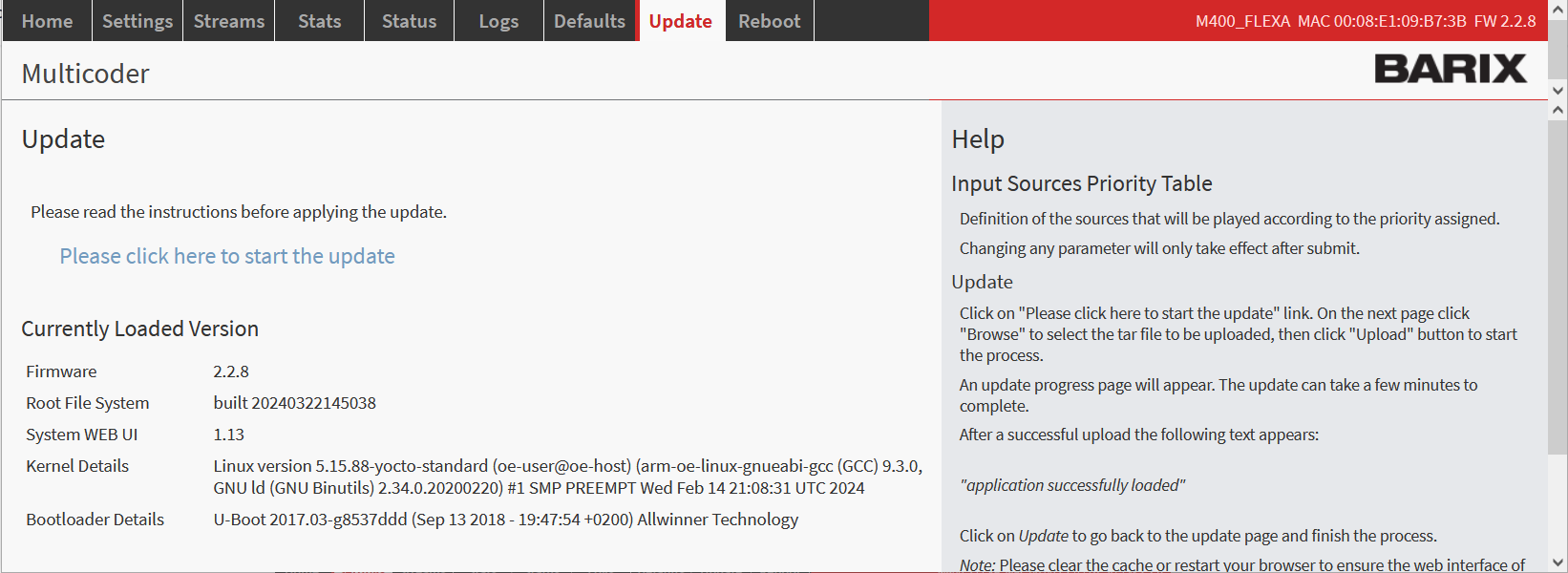
Update page
Reboot - web interface
Click "Reboot the device" to restart the device.
Thereafter the device will automatically start again.
The reboot is the process of power cycling the device (ON → OFF → ON). It’s a complete power cycle. The reboot can be performed from the web user interface or from the reset button located on the front panel of the device or by removing power for a few seconds.
Reboot - physical button
The reboot of the device from the button is performed by pressing the Reset button located on the front panel of the LX400 device for ~3 secs.
Compliance and further Information
This equipment has been tested and found to comply with the limits for a Class B digital device, pursuant to part 15 of the FCC Rules. These limits are designed to provide reasonable protection against harmful interference in a residential installation. This equipment generates, uses and can radiate radio frequency energy and, if not installed and used in accordance with the instructions, may cause harmful interference to radio communications. However, there is no guarantee that interference will not occur in a particular installation. If this equipment does cause harmful interference to radio or television reception, which can be determined by turning the equipment off and on, the user is encouraged to try to correct the interference by one or more of the following measures:
Reorient or relocate the receiving antenna.
Increase the separation between the equipment and receiver.
Connect the device into an outlet on a circuit different from that to which the receiver is connected.
Consult the dealer or an experienced radio/TV technician for help.
Safety and precaution recommendations apply. Find them in the download section at www.barix.com.

Find your distributor on this list for more hardware.
For questions that are extending the documentation, feel free to contact us on:
International: +41 434 33 22 22
USA: +1 866 815 0866
Email: support@barix.com
All information and the use of this product including all services are covered under the Barix Terms & Conditions and our Privacy Policy. Please follow the Safety and Precaution Recommendations. Barix is a ISO 9001:2015 certified company. All rights reserved. All information is subject to change without notice. All mentioned trademarks belong to their respective owners and are used for reference only.