Please make sure to first read the safety information in order to avoid hazards.
The scope of this document is to give a thorough introduction on the LX400 STL. At the end of this guide the user will be able to run a basic setup and have an audio stream playing.
LX400 STL runs the STL Flexa application. Refer to LX400 STL User Manual (https://help.barix.com/lx400-stl/lx400-stl-manual) for a complete explanation on the software functionalities.
Before you start using the LX400 STL
A few things you need to know before you can effectively use the LX400 STL broadcast encoder decoder.
What is FLEXA
The LX400 STL runs a firmware that is called FLEXA. STL is an application running on the FLEXA firmware. That should not concern you. Most important for you are the menus SETTINGS, CLIENT HOME and LOCAL CONFIG.
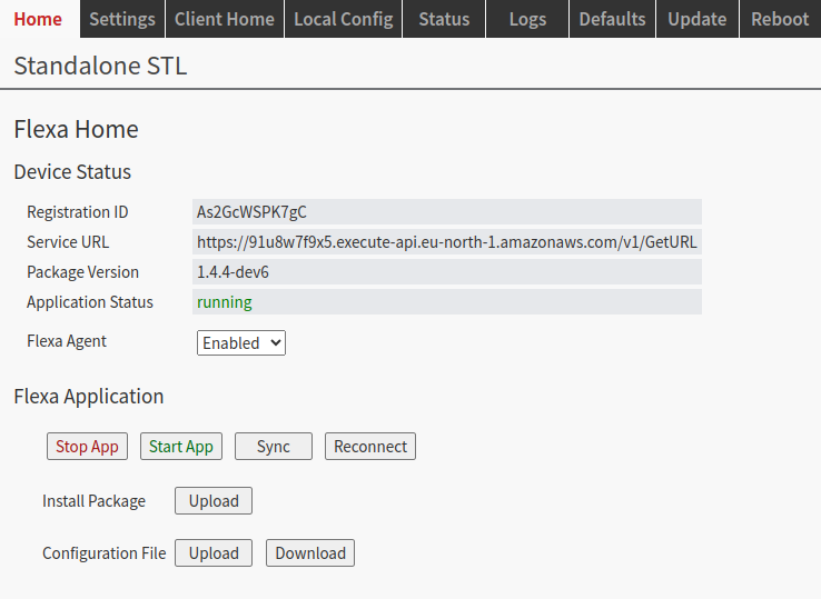
No need to press any of the buttons on the HOME screen. Key there is that it shows “Application Status running”.
When you enable the FLEXA AGENT, then the unit will call into the Internet (if it can reach it) and automatically get firmware updates. It also enable Portal Config via SUPICONF (see below).
To run the unit stand-alone with the local GUI for configurations, disable the FLEXA AGENT.
Important: If you have the FLEXA AGENT enabled, and then try to change the configuration you will get the following warning.
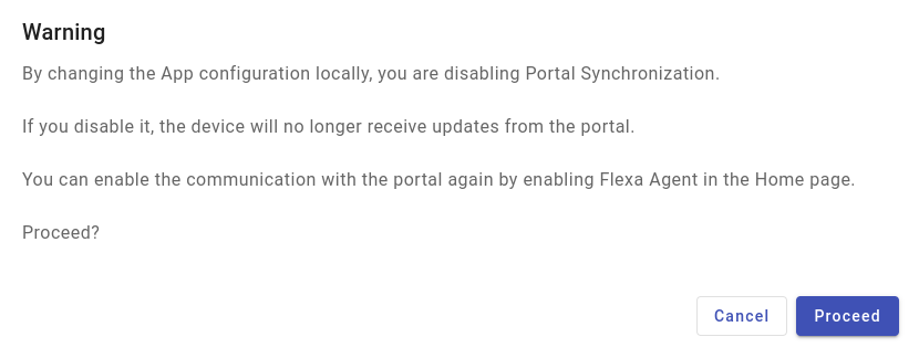
If you click "Proceed", then the FLEXA agent will be disabled, putting you back in stand-alone mode.
What is SUPICONF?
Your LX400 STL is SUPICONF ready. SUPICONF is a future portal solution by BARIX that allows you to configure the unit via a Web Portal instead of locally via Web GUI.
The Portal is available in Beta version and you can try it.
A key shortcomings of the Beta Version is that synchronization between the Portal and the device only happens once an hour. This will be improved to a much shorter reaction time in the final release.
Interested in SUPICONF?
If you are interested in SUPICONF and want to get an account, please contact the vendor who sold you the unit. They can enable your free SUPICONF account.
Package Content
-
LX400 device
-
Quick Install Guide
The LX400 STL is an audio over IP encoder with analog audio I/O and AES output on StudioHub (RJ45) connectors.
See here about StudioHub: https://studiohub.com.
Installation
STEP 1 Connect the Audio Equipment
The LX400 STL provides balanced line level analog audio I/O and AES output on StudioHub (RJ45) connectors, to be connected to a mixer, an FM modulator/transmitter, an amplifier, etc.
You can listen the IP address of the device directly after reboot played on the analog and digital audio output (https://help.barix.com/knowledgebase/what-is-sonicip).
STEP 2 Connect the network
Connect your LX400 STL to the network using a standard Ethernet cable (CAT5e or better) through the port labeled POE.
If you’ve a PoE switch or a PoE injector (802.3af compliant) you don’t need to use an external power supply.
STEP 3 Boot the device
After to have connected the Ethernet cable to a PoE device or to have plugged in the power supply, the device will boot:
-
Right after power-up left status LED is red (boot in process)
-
5s after power-up → left status LED starts blinking and right status LED is solid red
-
about 15s after power-up → Device announces its IP Address over the analog and digital audio output (take note to be able to enter the web interface later) → Left LED turns from red to green
-
about 30s after power up → Application is ready → both status LEDs are solid green
LX400 STL is ready to be configured.
Note:
You can connect PoE as well as an external power supply at the same time. The equipment will use the power sources as redundant sources without the need for interaction.
First Configuration
|
1 |
From a PC in the same network subnet of the device, use a web browser to access the web interface by typing the IP Address into your browser. There are two ways to find the IP address of the unit:
|
|
2 |
Login is required, by default user is "admin" and the password is provided on the sticker on the backside of the device (PW label). 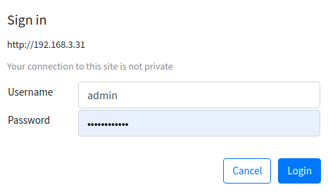
|
|
3 |
On the “Home” page you get information about the application status.
|
|
4 |
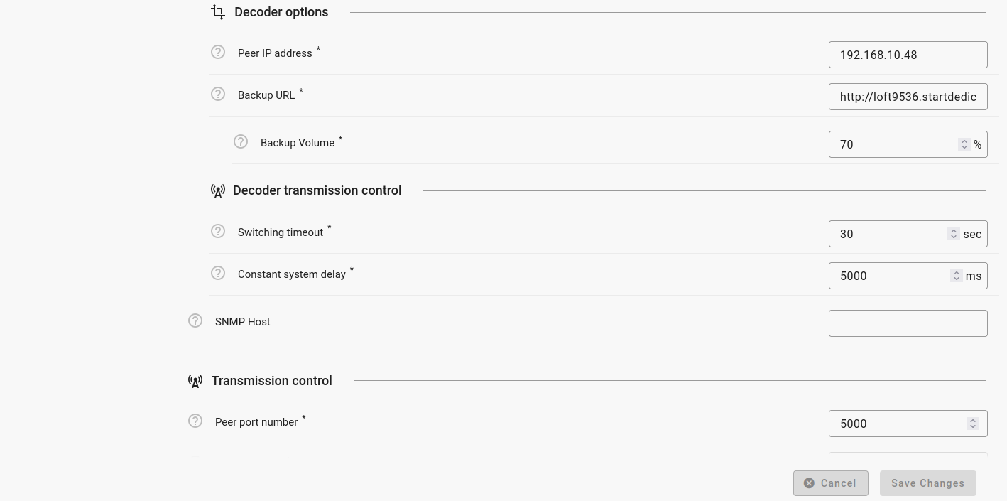
Go to the “Local Config” where you can configure the STL application settings. First of all configure the Device type (Encoder or Decoder). 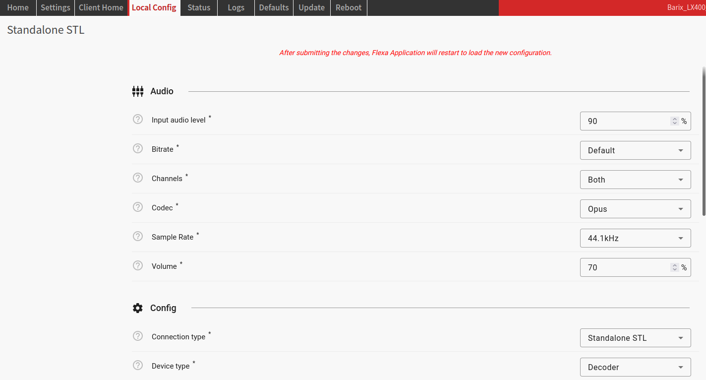
|
|
5 |
When done, click “Save Changes ”. Important: If you have the FLEXA AGENT enabled, and then try to change the configuration you will get the following warning (see above).
|
Hardware functionality
|
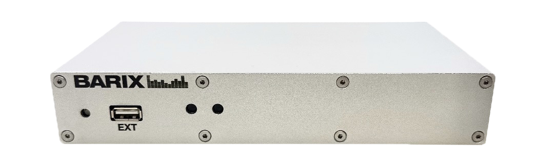
Front View
|
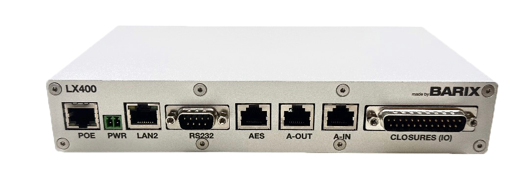
Rear View
|
||
|
RESET button |
Short press while powered (1s - 9s) → Reboots the device Long press while powered (10s - 19s) → Hard reset to defaults (including network settings) Press and hold for 30s while powering up → Rescue process triggered: device will connect to the Barix update server and install the latest firmware |
POE (Ethernet 10/100 ) |
Fast Ethernet network connection on RJ45 and PoE (802.3af) |
|
EXT Port |
to connect external USB devices,
|
PWR (Power) |
Power connector (terminal block) |
|
LEDs (see table below) |
As per picture above:
|
LAN2 |
Not supported at the moment |
|
|
|
RS232 |
Metadata I/O |
|
|
|
AES (Digital Audio Output) |
StudioHub RJ45 connector |
|
|
|
A-IN (Analog Audio Input) |
StudioHub RJ45 connector
|
|
|
|
A-OUT (Analog Audio Output) |
StudioHub RJ45 connector
|
|
|
|
CLOSURES (IO) |
Input contacts and relay outputs |
STATUS LED Behavior
|
Status LEDs description |
Left LED
|
Left LED
|
Right LED
|
Right LED
|
Comments |
|---|---|---|---|---|---|
|
System not powered |
OFF |
OFF |
OFF |
OFF |
|
|
System booting |
|
RED |
OFF |
|
LED1 blinks slowly during the boot up process |
|
System in Rescue mode |
|
ORANGE |
OFF |
|
As soon as device enters rescue mode, LED1 starts blinking YELLOW |
|
Factory defaults setting (RESET button pressed >10s) |
|
GREEN(fast) |
OFF |
|
After 10s of holding RESET button pressed, LED1 starts blinking fast GREEN to indicate that the RESET button can be released and that the default factory settings will be applied (incl. Network settings) |
|
System ready |
GREEN |
|
(see lines below) |
(see lines below) |
Check the descriptions below to see how the LEDs are supposed to behave once the system is “ready” |
|
Application not running |
GREEN |
|
RED |
|
|
|
Application running |
GREEN |
|
GREEN |
|
|
|
Downloading / Installing Firmware |
|
ORANGE |
GREEN |
|
|
|
uSD Card Failure |
|
ORANGE |
|
GREEN |
After power up it takes 38s for this pattern to appear |
Compliance and further Information
This equipment has been tested and found to comply with the limits for a Class B digital device, pursuant to part 15 of the FCC Rules. These limits are designed to provide reasonable protection against harmful interference in a residential installation. This equipment generates, uses and can radiate radio frequency energy and, if not installed and used in accordance with the instructions, may cause harmful interference to radio communications. However, there is no guarantee that interference will not occur in a particular installation. If this equipment does cause harmful interference to radio or television reception, which can be determined by turning the equipment off and on, the user is encouraged to try to correct the interference by one or more of the following measures:
-
Reorient or relocate the receiving antenna.
-
Increase the separation between the equipment and receiver.
-
Connect the device into an outlet on a circuit different from that to which the receiver is connected.
-
Consult the dealer or an experienced radio/TV technician for help.
Safety and precaution recommendations apply. Find them in the download section at www.barix.com

Find your distributor on this list for more hardware.
For questions that are extending the documentation, feel free to contact us on:
International: +41 434 33 22 22
USA: +1 866 815 0866
Email: support@barix.com
All information and the use of this product including all services are covered under the Barix Terms & Conditions and our Privacy Policy. Please follow the Safety and Precaution Recommendations. Barix is a ISO 9001:2015 certified company. All rights reserved. All information is subject to change without notice. All mentioned trademarks belong to their respective owners and are used for reference only.