The scope of this document is to give a thorough introduction on the Annuncicom MPI400. At the end of this guide the user will be able to run a basic setup and have an audio stream playing.
Annuncicom MPI400 runs the IP Audio Client software. Refer to the IP Audio Client user manuals (Standard Mode - AES67 Mode) for a complete explanation on the software functionalities.
Package Content
-
MPI400 device (including screw terminal blocks)
-
Quick Install Guide
The Barix Annuncicom MPI400 is an audio over IP decoder, PoE or externally powered, offering a multitude of interfaces:
-
1x 10/100 MB Ethernet with PoE support (IEEE 802.3af)
-
1x 24VDC power input
-
1x Audio output connection that can drive: 1w@8ohm speaker OR a line level balanced input
-
1x 18V Phantom power microphone Input
-
1x 2.7V Microphone input
-
1x Unbalanced line level Input
-
2x Digital inputs (dry contact)
-
1x Normally closed relay
-
1x Normally opened relay
-
2x USB Type A
-
1x Headphone out on 3.5mm trs
Installation
STEP 1 Connect the Audio Equipment
The Annuncicom MPI400 provides audio output on one of these connections: headphone, speaker / line.
STEP 2 Connect the network
Connect your Annuncicom MPI400 to the network using a standard Ethernet cable (CAT5e or better).
STEP 3 Power up
Annuncicom MPI400 supports the PoE standard. If a PoE switch is not available consider to use a 24V external power supply. At boot the device will
-
Light up status LEDs, both red (boot in process)
-
15s after power up → Device announces its IP Address (take note to be able to enter the web interface later) → Left LED turns from red to green
-
35s after power up → Application is ready → Right LED turns from red to green
Annuncicom MPI400 is ready to be used.
First Configuration - Play Barix Radio
|
1 |
From a PC in the same network subnet of the device, use a web browser to access the web interface by typing the IP Address into your browser (the one noted during boot) |
|
2 |
Login is required, by default user is "admin" and the password is provided on the sticker on the backside of the device (PW label) 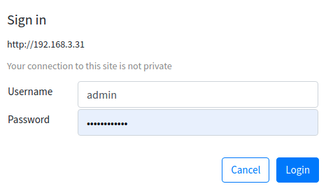
|
|
3 |
Navigate to the Source page - by default the application runs InformaCast (if licensed) and SynApps. 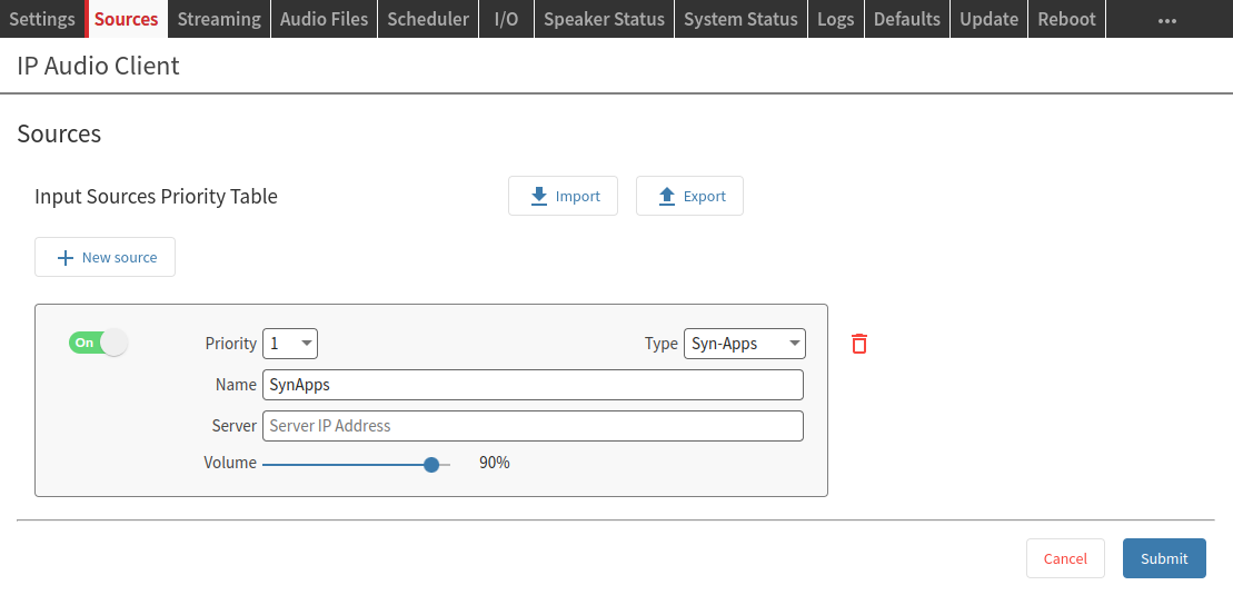
|
|
4 |
Select Barix Radio from the Type drop-down menu. Barix Radio is a source type pre-configured to play music from https://www.barix.com/radio.m3u - Change the source Name into “Barix Radio” (not mandatory) |
|
5 |
Click on SUBMIT → After few seconds music will play |
|
6 |
Check out the Speaker Status page to monitor the playback. When the source plays the corresponding layer turns green 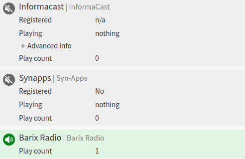
|
Hardware functionality
|
Front View 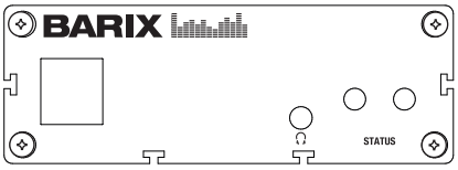
|
Rear View 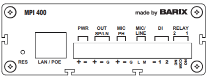
|
||
|
2x USB |
Type A USB Ports |
RESET button |
Short press while powered (1s - 9s) → Reboots the device Long press while powered (10s - 19s) → Hard reset to defaults (including network settings) Press and hold for 30s while powering up → Rescue process triggered: device will connect to the Barix update server and install the latest firmware |
|
Headphone |
3.5mm trs headphone output |
10/100 ETH |
Fast Ethernet network connection on RJ45 |
|
LEDs (see table below) |
As per picture above:
|
Power |
2 ways detachable screw terminal block 24VDC Input - 12W max. consumption |
|
|
|
Out Sp/Ln |
3 ways detachable screw terminal block. Capable of driving both speaker level and line level inputs.
|
|
|
|
MIC PH |
5 ways detachable screw terminal block (pins 1 -3 from left to right “+”,”-”,”G”) Balanced 18V Phantom Microphone Input |
|
|
|
LINE |
5 ways detachable screw terminal block (pins 3 -4 from left to right, “G”,”L”) Unbalanced Line Level Input |
|
|
|
MIC |
5 ways detachable screw terminal block (pins 3 -5 from left to right, “G”,”M”) Unbalanced 2.1V bias Microphone Input |
|
|
|
DI |
2x Digital Inputs (dry contact) |
|
|
|
REL |
1x Normally Open Relay, 30V 0.5A 1x Normally Closed Relay, 30V 0.5A |
IO Operations
-
Digital Input Operation modes: Configurable individually for each dry contact input available
-
SIP: initiate calls, accept incoming calls, hangup calls when the input is closed.
-
SIP “Press-Hold-Release”: same as SIP with the difference that any state change of the input triggers the action to perform.
-
SIP Refer Blind Transfer: Transfer a call to the configured extension
-
-
Relay Output activation: Configurable individually for each relay output available
-
Relay activation upon audio presence on selected audio sources
-
Relay activation from REST API call (if enabled in the configuration)
-
STATUS LED Behavior
|
Status LEDs description |
Left LED
|
Left LED
|
Right LED
|
Right LED
|
Comments |
|---|---|---|---|---|---|
|
System not powered |
OFF |
OFF |
OFF |
OFF |
|
|
System booting |
|
RED |
OFF |
|
LED1 blinks slowly during the boot up process |
|
System in Rescue mode |
|
ORANGE |
OFF |
|
As soon as device enters rescue mode, LED1 starts blinking YELLOW |
|
Factory defaults setting (RESET button pressed >10s) |
|
GREEN (fast) |
OFF |
|
After 10s of holding RESET button pressed, LED1 starts blinking fast GREEN to indicate that the RESET button can be released and that the default factory settings will be applied (incl. Network settings) |
|
System ready |
GREEN |
|
(see lines below) |
(see lines below) |
Check the descriptions below to see how the LEDs are supposed to behave once the system is “ready” |
|
Application not running |
GREEN |
|
RED |
|
|
|
Application running |
GREEN |
|
GREEN |
|
|
|
Downloading / Installing Firmware |
|
ORANGE |
GREEN |
|
|
For more details on IP Audio Client, the software running on Annuncicom MPI400 consult the IP Audio Client user manual.
Compliance and further Information
This equipment has been tested and found to comply with the limits for a Class B digital device, pursuant to part 15 of the FCC Rules. These limits are designed to provide reasonable protection against harmful interference in a residential installation. This equipment generates, uses and can radiate radio frequency energy and, if not installed and used in accordance with the instructions, may cause harmful interference to radio communications. However, there is no guarantee that interference will not occur in a particular installation. If this equipment does cause harmful interference to radio or television reception, which can be determined by turning the equipment off and on, the user is encouraged to try to correct the interference by one or more of the following measures:
-
Reorient or relocate the receiving antenna.
-
Increase the separation between the equipment and receiver.
-
Connect the device into an outlet on a circuit different from that to which the receiver is connected.
-
Consult the dealer or an experienced radio/TV technician for help.
Safety and precaution recommendations apply. Find them in the download section at www.barix.com

Find your distributor on this list for more hardware.
For questions that are extending the documentation, feel free to contact us on:
International: +41 434 33 22 22
USA: +1 866 815 0866
Email: support@barix.com
All information and the use of this product including all services are covered under the Barix Terms & Conditions and our Privacy Policy. Please follow the Safety and Precaution Recommendations. Barix is a ISO 9001:2015 certified company. All rights reserved. All information is subject to change without notice. All mentioned trademarks belong to their respective owners and are used for reference only.