The scope of this document is to give a thorough introduction on the RetailPlayer M400.
RetailPlayer M400 runs the RetailPlayer software. Refer to the RetailPlayer user manual for a complete explanation on the software functionalities.
Package Content
-
M400 device
-
Audio cable with RCA connectors
-
Power Supply Unit (depends on the PN purchased)
-
Quick Install Guide
The Barix RetailPlayer M400 is an audio over IP decoder with a line-level output on stereo RCA connections.
Installation
STEP 1 Connect the Audio Equipment
The RetailPlayer M400 provides an unbalanced line level output (nominal at 0dBu), to be connected to a mixer, a DSP, an amplifier, etc.
STEP 2 Connect the network
Connect your RetailPlayer M400 to the network using a standard Ethernet cable (CAT5e or better).
STEP 3 Connect the power supply
Plug the power into the power connector on the back panel of the device. The device will boot:
-
Right after power-up both status LEDs are red (boot in process)
-
15s after power-up → Device announces its IP Address (take note to be able to enter the web interface later) → Left LED turns from red to green
-
35s after power up → Application is ready → Right LED turns from red to green
RetailPlayer M400 is ready to be configured. Refer to the Quick Install Guide for a fast introduction on how to connect the unit with the Portal and play music.
Hardware functionality
|
Front View 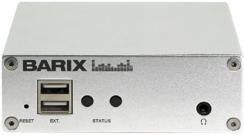
|
Rear View 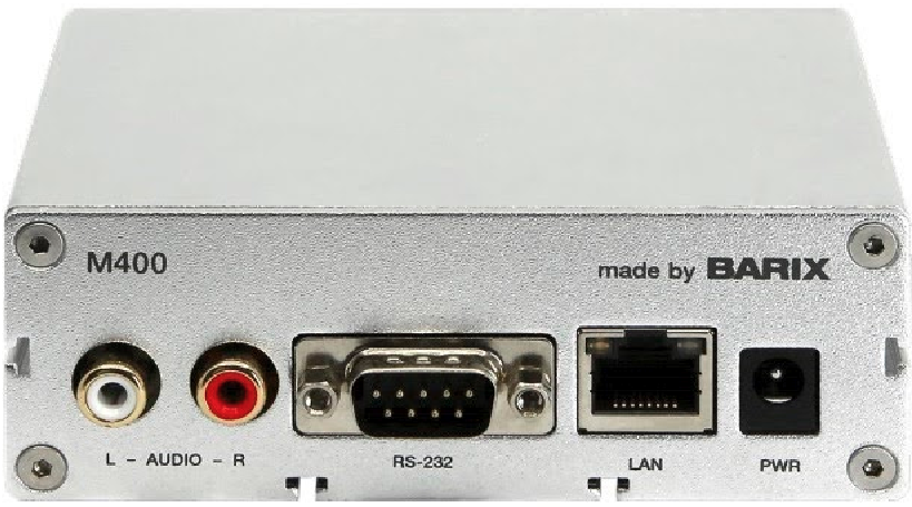
|
||
|
RESET button |
Short press while powered (1s - 9s) → Reboots the device Long press while powered (10s - 19s) → Hard reset to defaults (including network settings) Press and hold for 30s while powering up → Rescue process triggered: device will connect to the Barix update server and install the latest firmware |
Audio |
2x RCA audio output connectors - unbalanced Nominal output: 0dBu |
|
2x USB Ports |
Play audio files from USB triggered via UDP network command |
RS232 |
Serial port - Currently not used by the RetailPlayer application |
|
LEDs (see table below) |
As per picture above:
|
10/100 |
Fast Ethernet network connection on RJ45 |
|
Headphone |
Reflects the main audio output on a 3.5mm trs connector made for headphone monitoring |
Power |
Power connector, barrel style 6.5x1.5mm central positive |
STATUS LED Behavior
|
Status LEDs description |
Left LED
|
Left LED
|
Right LED
|
Right LED
|
Comments |
|---|---|---|---|---|---|
|
System not powered |
OFF |
OFF |
OFF |
OFF |
|
|
System booting |
|
RED |
OFF |
|
LED1 blinks slowly during the boot up process |
|
System in Rescue mode |
|
ORANGE |
OFF |
|
As soon as device enters rescue mode, LED1 starts blinking YELLOW |
|
Factory defaults setting (RESET button pressed >10s) |
|
GREEN
|
OFF |
|
After 10s of holding RESET button pressed, LED1 starts blinking fast GREEN to indicate that the RESET button can be released and that the default factory settings will be applied (incl. Network settings) |
|
System ready |
GREEN |
|
(see lines below) |
(see lines below) |
Check the descriptions below to see how the LEDs are supposed to behave once the system is “ready” |
|
Application not running |
GREEN |
|
RED |
|
|
|
Application running - Portal connection established |
GREEN |
|
GREEN |
|
The application is running and the device established connection to the RetailPlayer Portal |
|
Application running - Portal connection not established |
GREEN |
|
|
GREEN |
The application is running but the device is not able to establish connection with the RetailPlayer Portal |
|
Downloading / Installing Firmware |
|
ORANGE |
GREEN |
|
|
Compliance and further Information
This equipment has been tested and found to comply with the limits for a Class B digital device, pursuant to part 15 of the FCC Rules. These limits are designed to provide reasonable protection against harmful interference in a residential installation. This equipment generates, uses and can radiate radio frequency energy and, if not installed and used in accordance with the instructions, may cause harmful interference to radio communications. However, there is no guarantee that interference will not occur in a particular installation. If this equipment does cause harmful interference to radio or television reception, which can be determined by turning the equipment off and on, the user is encouraged to try to correct the interference by one or more of the following measures:
-
Reorient or relocate the receiving antenna.
-
Increase the separation between the equipment and receiver.
-
Connect the device into an outlet on a circuit different from that to which the receiver is connected.
-
Consult the dealer or an experienced radio/TV technician for help.
Safety and precaution recommendations apply. Find them in the download section at www.barix.com

Find your distributor on this list for more hardware.
For questions that are extending the documentation, feel free to contact us on:
International: +41 434 33 22 22
USA: +1 866 815 0866
Email: support@barix.com
All information and the use of this product including all services are covered under the Barix Terms & Conditions and our Privacy Policy. Please follow the Safety and Precaution Recommendations. Barix is a ISO 9001:2015 certified company. All rights reserved. All information is subject to change without notice. All mentioned trademarks belong to their respective owners and are used for reference only.