Congratulation for buying the Exstreamer SoundScape.
We hope you find a quick start with this product. If you have any feedback or questions, write us at support@barix.com.
Safety Precautions
Please make sure to first read the safety information in order to avoid hazards.
Package Content and Accessories
Package contents
-
Exstreamer SoundScape
-
Power supply (except NoPSU version)
-
MicroSD internal memory card (except NoSD version)
Needed materials
-
Earphone
-
RCA Stereo cable
-
Network cable
-
Serial cable
Device functionality
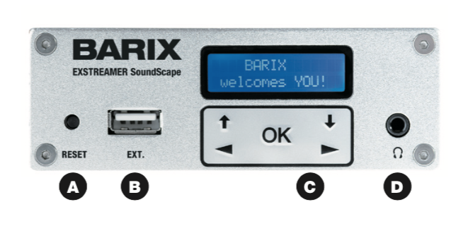
A - Reset button
A brief press of the button will reset the device. Holding the reset button pressed in for 10 seconds (until the red LED starts flashing) will reset the device and restore the factory default settings when the button is released.
The reset button can ge disabled from the web UI when logged in as Admin.
B - EXT.
Interface to connect USB 2.0 devices, e.g. for flash memory sticks (not supplied). This can be used for updating the device’s firmware or for cloning the content of the USB to the internal microSD. For more details please refer to the User Manual.
C - Status LEDs / or Display and Keypad
Green and red LEDs or Display and Keypad for status display and local control of playback and device configurati- on. Keypad operation can be disabled from the web user interface when logged in as Admin.
D - Headphone out
Standard stereo mini jack (3.5 mm)
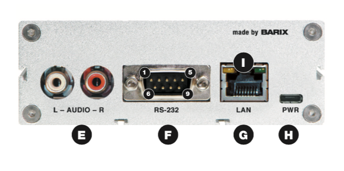
E - Line out
Stereo RCA line outputs
F - RS-232 serial port
(DSub 9 pin male)
|
Pin |
Description |
|---|---|
|
1 |
Not connected |
|
2 |
Receive Data [RxD] |
|
3 |
Transmit Data [TxD] |
|
4 |
V+ 5V, 100mA max |
|
5 |
Ground [GND] |
|
6 |
Not connected |
|
7 |
Ready to Send [RTS] |
|
8 |
Clear to Send [CTS] |
|
9 |
Not connected |
G - LAN port 10/100
(RJ45 Ethernet socket)
|
Pin |
Description |
|---|---|
|
1 |
Tx + |
|
2 |
Tx - |
|
3 |
Rx + |
|
4 |
Not connected |
|
5 |
Not connected |
|
6 |
Rx - |
|
7 |
Not connected |
|
8 |
Not connected |
H - Power
Standard microUSB, 5 VDC, 2 Watt max.
I - LAN status LEDs
Green LED for Link status, yellow LED for Activity status
Installation
STEP 1
Plug a standard (straight) network cable (f, not included) into the network port (G) of the Exstreamer and the other end into the hub or switch. A crossover network cable (not included) can also be used for a direct connection to the PC.
STEP 2
-
Plug standard headphones or the earphone (d, not included) into the headphone output (D) and listen.
-
Plug the RCA cable (e) into the LINE OUT outputs (E) and connect the cable to inputs of your mixing console or monitoring device.
-
Remove plastic strip coming out next to RS-232 connector (F) to initialize RTC battery.
STEP 3
Connect the Power supply (b) to the device (socket H) and then to an appropriate electrical outlet.
STEP 4
-
The Exstreamer SoundScape will now acquire an IP address and announce it over the audio outputs (SonicIP®). DHCP is the default method for acquiring automatically an IP address from the DHCP server in the network.
-
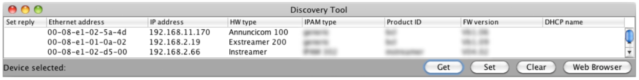
If audio outputs were not connected in Step 2 and the SonicIP® announcement of acquired IP address was not heard, it is recommended to use the “Barix Discovery Tool” Java application (download the latest version from www.barix.com under “Software Tools” in “Downloads” section) on your computer (Windows, Mac or Linux) and click the “Get” button to find out which IP address the device has obtained (see picture at the bottom of the page). Make sure that the Ethernet address (MAC) matches the one of the device (see label on the bottom of the device).
Once the IP address of the Exstreamer SoundScape is known, it is time to proceed to the next section for “Net- work configuration via web browser”.
If the device’s current IP address was not discovered with the previous steps, see section ”Troubleshooting”.
Network configuration from web browser
The SoundScape application is using DHCP by default so it doesn’t require any initial network configuration. If a static (fixed) IP address is required, please follow steps 2 and 3, otherwise these steps can be skipped.
STEP 1
Open a web browser and type the IP address that was announced by the Exstreamer SoundScape during boot-up (e.g.: 192.168.0.12) and press Enter.
STEP 2
Login as “Admin” (default password “Abarix”) and click on the “Network” tab. Select “Static IP” on the drop-down menu next to “Protocol” field (by default is set to “DHCP”).
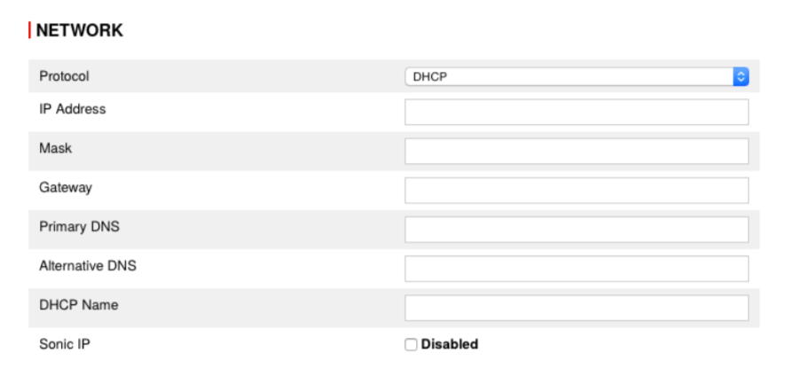
STEP 3
Set the IP Address, Netmask, Gateway, Primary DNS and Alternative DNS.
STEP 4
Set the SoundScape Portal IP address where the Sound- Scape Player should be calling in for registration and updates. By default this will be set to communicate to the BARIX hosted SoundScape Portal.
STEP 5
Click “Submit” for the changes to take effect.
Please download the SoundScape User Manual for more details about further configuration options.
Troubleshooting
-
If the status LEDs (C) stay dark check the powercabling (installation step 3).
-
Check if the green LINK LED (I) is lit, if it is not thencheck your network cabling (network port G)
-
If current device settings are uncertain, the device can revert to its factory defaultsby pressing the Reset button (A) until the red status LED (C) blinks (takes about 10 seconds). The device will restore the factory defaults once the button is released.
Compliance and further Information
This equipment has been tested and found to comply with the limits for a Class B digital device, pursuant to part 15 of the FCC Rules. These limits are designed to provide reasonable protection against harmful interference in a residential installation. This equipment generates, uses and can radiate radio frequency energy and, if not installed and used in accordance with the instructions, may cause harmful interference to radio communications. However, there is no guarantee that interference will not occur in a particular installation. If this equipment does cause harmful interference to radio or television reception, which can be determined by turning the equipment off and on, the user is encouraged to try to correct the interference by one or more of the following measures:
-
Reorient or relocate the receiving antenna.
-
Increase the separation between the equipment and receiver.
-
Connect the device into an outlet on a circuit different from that to which the receiver is connected.
-
Consult the dealer or an experienced radio/TV technician for help.
Safety and precaution recommendations apply. Find them in the download section at www.barix.com

Find your distributor on this list for more hardware.
For questions that are extending the documentation, feel free to contact us on:
International: +41 434 33 22 22
USA: +1 866 815 0866
Email: support@barix.com
All information and the use of this product including all services are covered under the Barix Terms & Conditions and our Privacy Policy. Please follow the Safety and Precaution Recommendations. Barix is a ISO 9001:2015 certified company. All rights reserved. All information is subject to change without notice. All mentioned trademarks belong to their respective owners and are used for reference only.