What is the RackBox?
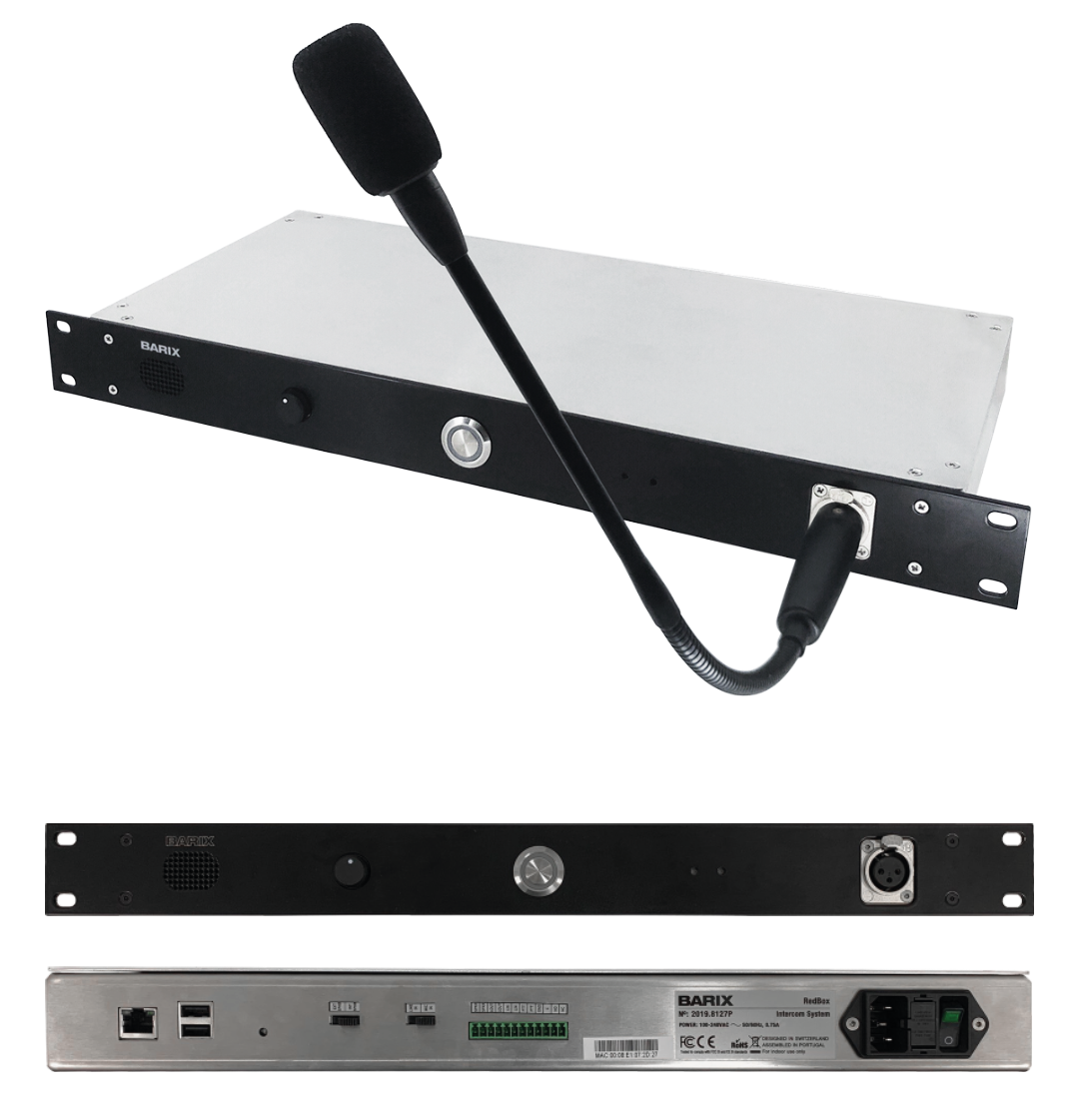
The RackBox is an IP based intercom station for any-to-all communication over the local or wide area network. Its setup consists of an unlimited number of 19’’ rack mountable RackBoxes, a message routing device (AudioSpread) and a web based management server (RBMS). The source can be limited to act as receiver or sender. Multi source set ups are possible.
The system is designed to be maintenance free, low power (15W) and long lasting. If additional features are requested, the device is ready to receive updates through the management server or an USB stick. The interface provides a graphical overview of the system on a map, as well as showing a status list to monitor station changes onsite.
Main Features
-
Runs on standard IP networks or the internet
-
Low bandwidth requirements
-
Easy to install
-
Simple One-Push button to make an announcement
-
Management server for easy system monitoring and configuration
-
Supports XLR microphone
-
Updatable over the network and by USB Stick
-
Relay output
RackBox Installation Guide
Start by making sure that the RBMS and AudioSpread are up and running to be able to complete the RackBox setup.
RackBox Power-up
Connect the power and ethernet cables to the unit. Then, turn it ON by with the the switch on the back side and wait for the device to boot up.
The power switch is working if the Green light is ON.
While the device is booting, you will hear the device IP address being announced, which will be 192.168.123.123 in a brand new device or the IP address already assigned to it by means of the RBMS.
Providing the first configuration
When the device has booted and the application has started, you will hear a lady’s voice asking to insert an USB stick with the first configuration. This USB stick should only contain a file named settings.json (a JSON file) with the following content:
-
ServerIP: The IP address of the RBMS. This IP will be stored in non-volatile storage and overwritten if the RBMS IP address changes.
-
TestIP: The IP address which will be assigned to the device for the first contact to the RBMS. It will not be stored.
-
TestNM: The subnet Mask which will be assigned to the device for the first contact to the RBMS. It will not be stored.
-
TestRT: The router IP address (Default Gateway) which will allow the device to connect to the RBMS. It will not be stored.
Example JSON file
{
  "ServerIP": "192.168.1.45",
  "TestIP": "192.168.1.202",
  "TestNM": "255.255.255.0",
  "TestRT": "192.168.1.254"
}
With this information provided in the JSON file, the device will contact the RBMS for the first time. IT will ask for the AudioSpread test stream IP Address, which must be provided as explained on the RBMS Functionality instructions. Once the device has contacted the portal and a valid IP address has been provided, it will enter test mode and it will appear in the “New Devices“ tab of the RBMS. By this time, the USB stick can be removed from the device to another, as it is no longer needed.
Test Mode
The test mode is intended to fully test the device capabilities. The following test can be done one the device:
-
No action: The device will play the provided test stream and blink the main LED at 1Hz frequency.
-
Pushing the front button will trigger the push to talk signal (also possible by the external trigger). The device will start recording the selected audio input which is dependent of the selector position in the back which toggles between the line in and the built-in XLR microphone input.
-
Releasing the button OR if the recorded time reaches 30 seconds, the device will start reproducing the recorded content.
-
Content plays, and after finishing it, the device will jump to play the test stream (1. again). Note: If the push to talk signal is triggered before the recorded audio file is over, it will start recording again, overwriting the previous file.
Put the device into operational mode
After the test is completed successfully, please go to the RBMS in order to make the device operational as explained in the RBMS manual.
Once this action has been done and the device has reached the server, it will exit the test mode by announcing so. It will perform a reboot with the settings assigned in the portal. Wait approximately 30 seconds for the reboot to happen or manually do it by using the main power switch OFF/ON.
Operational mode
By now the device should have already a valid configuration and know how to reach all the elements involved in the system.
On boot, it will announce again its IP address and the push to talk LED will turn ON. This means the device is ready to listen incoming streams and if it is a source, to stream.
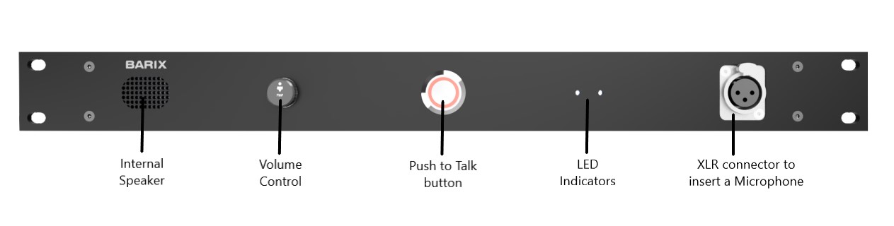
Front Interfaces
On the front of the device are the internal speaker (1W RMS), the XLR Microphone connector (with 9V phantom power), the Status LED, the Push to talk button and the the knob for the volume control. The volume knob is only for the internal front speaker, not for the audio outputs on the backside .
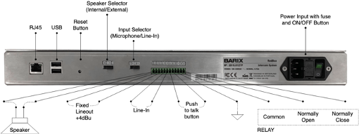
Rear Connections
The device has several possibilities to connect external accessories, it can be connected a different push button, speaker or simply power a signalling light into the relay output. It is also present a balanced line level input and an output which has a fixed +4dBu gain. Below can be found a diagram and the specifications.
|
|
Connection |
Description |
|
|---|---|---|---|
|
1 |
Independent Connector |
RJ45 |
Internet connection |
|
2 |
Independent Connector |
USB |
USB2.0 Type A connection to use with initial configurations USB Stick |
|
3 |
Independent Connector |
Reset Button |
Press Button to use when a factory reset is needed |
|
4 |
Independent Connector |
Speaker Selector |
A manual selector to choose which speaker will be used between internal/external |
|
5 |
Independent Connector |
Input Selector |
A manual selector to choose which input will be used between microphone or LineIn |
|
6 |
PIN1: - PIN2: + |
Speaker |
This gives the option to use an external speaker instead of the built-in one. Remember that still need to use the manual switch to choose between the external or internal speaker. |
|
7 |
PIN3: - PIN4: + |
Line Out |
It's basically a feed of a balanced audio level fixed +4dBu signal use accordingly with your needs. No need of selection as it is always available. |
|
8 |
PIN5: - PIN6: + |
Line In |
A balanced audio input that can work instead of the mic. Remember to use the manual switch to select this source as the feed for the transmission. Note: It's still necessary press the push button to initiate the transmission |
|
9 |
PIN7: - PIN8: + |
Push to talk Button |
You can add another push to talk button |
|
10 |
PIN9: Chassis GND |
Ground |
Typically connected to the rack-mount structures |
|
11 |
PIN10: COMMON PIN11: Normally Open PIN12: Normally Closed |
Relay Output |
The relay is a SPDT Relay, meaning that you have ‘Common’ (usually labeled COM), ’Normally Closed’ (NC) and ‘Normally Open’ (NO) terminals. When the relay is deactivated (no output), the connection by the relay is done between COM and NC. When the relay activates, it breaks that connection and makes a connection between COM and NO. |
Factory Reset
At any time, you can reset the station to its initial (delivery) state. To do so, with the help of a pen or a thin object, just press the small button (SW3) on the back right side (near the USB plugs) of the device until the green LED starts to blink. This action will take approximately 10 seconds. After the LED starts blinking, the device will reboot and boot as a new one. If you release the button before this time interval, nothing will happen.
Updates
At anytime you can update the RackBox with an USB stick containing a .zip file provided by Barix. Plug the USB stick into the USB ports available on the back right side of the device and the update will happen automatically.
There is a send command feature available in the RBMS (described in the RBMS manual) that could be used to launch an update to specific or all the units that communicate with the server.
Compliance and further Information
This equipment has been tested and found to comply with the limits for a Class B digital device, pursuant to part 15 of the FCC Rules. These limits are designed to provide reasonable protection against harmful interference in a residential installation. This equipment generates, uses and can radiate radio frequency energy and, if not installed and used in accordance with the instructions, may cause harmful interference to radio communications. However, there is no guarantee that interference will not occur in a particular installation. If this equipment does cause harmful interference to radio or television reception, which can be determined by turning the equipment off and on, the user is encouraged to try to correct the interference by one or more of the following measures:
-
Reorient or relocate the receiving antenna.
-
Increase the separation between the equipment and receiver.
-
Connect the device into an outlet on a circuit different from that to which the receiver is connected.
-
Consult the dealer or an experienced radio/TV technician for help.
Safety and precaution recommendations apply. Find them in the download section at www.barix.com

Find your distributor on this list for more hardware.
For questions that are extending the documentation, feel free to contact us on:
International: +41 434 33 22 22
USA: +1 866 815 0866
Email: support@barix.com
All information and the use of this product including all services are covered under the Barix Terms & Conditions and our Privacy Policy. Please follow the Safety and Precaution Recommendations. Barix is a ISO 9001:2015 certified company. All rights reserved. All information is subject to change without notice. All mentioned trademarks belong to their respective owners and are used for reference only.