Package Content and Accessories
Package contents
-
Instreamer ICE
-
Power supply
-
RCA stereo cable
Required Cable Set
-
Ethernet cable (not included)
-
Earphones/headsets (not included)
Safety Precautions
Please make sure to first read the safety information in order to avoid hazards.
Device functionality
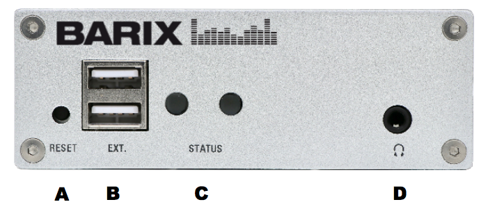
Front view
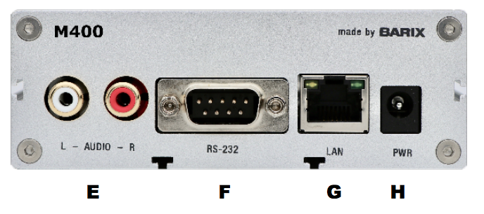
Rear view
A - Reset Button
Press and hold the reset button until LED1 starts blinking (i.e. for approx. 10 seconds). Release it and the device will be rebooted and the factory default settings will be restored.
B - EXT. ports
to connect USB 2.0 devices (for future purposes)
C - Status LEDs
LED1 shows system status:
-
Red – blinking fast: early startup
-
Red – solid: first stage boot loader
-
Red – blinking slow: system booting
-
Green – solid: system up and running
-
Green – blinking: restoring factory defaults
LED2 shows application status
-
Black – server stopped
-
Red – overmodulated
-
Orange – no incoming signal
-
Green – solid: ok but no audio stream
-
Green – blinking: audio stream running
D - Headphone out
Standard stereo mini jack (3.5mm)
E - Line-in
RCA inputs for audio sources (mono inputs per unit - white: Left Line input; red: Right Line input)
F - RS-232
Serial interface port with standard D-sub 9- pin male connector. Used to insert metadata to the internal Icecast server.
|
Pin |
Description |
Pin |
Description |
|---|---|---|---|
|
1 |
Not connected |
6 |
Not connected |
|
2 |
Receive Data [RxD] |
7 |
Ready to Send [RTS] |
|
3 |
Transmit Data [TxD] |
8 |
Clear to Send [CTS] |
|
4 |
V+ 5V, 100mA max |
9 |
Not connected |
|
5 |
Ground [GND] |
|
|
G - LAN port
RJ45 connector for 10/100 Ethernet
H - Power Barrel
5.5 x 2.1 mm female connector 5VDC 2A input power (positive polarity)
Hardware Installation
Step 1
Plug the earphone (a) or standard headphones into the mini jack (D).
Step 2
Plug a standard network cable (e) into the network port (G) of the Instreamer ICE and the other end into your switch. You can also use a crossover network cable (not included) for a direct connection to your PC.
Step 3
Connect the Power supply (b) to the device (H) and then to the electricity grid.
Step 4
Connect the RCA stereo cable (c) between the Line-in (E) and your feeding audio source.
Step 5
-
The Instreamer ICE will now acquire an IP address (DHCP is required) and announce it over the headphones output
-
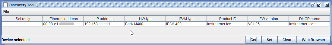
If you did not connect any "earphone" in step 1, use the “Barix Discovery Tool” Java application (download the latest version from barix.com) on your computer (Windows, Mac or Linux) and click the “Get” button to find out which IP address was attributed to the device (see picture at the bottom of the page). Make sure that the Ethernet address (MAC) matches that of your device (see label on the bottom of the device). You may also use the Discovery Tool to change the device's IP address by double-clicking the existing IP, modifying it and clicking on "Set".
Device configuration
Step 1
Open a browser and point it at the IP address of your device.
Step 2
To login to your device for the first time, check the bottom of your device for a sticker: on it, you will find the password that works with both profiles: "admin" and "user".
Step 3
If you wish, you can go to "Status", click on "Manage Passwords" and change the password of the "admin" and "user" profiles. The default password for the "Icecast admin" is barix_icecast
Step 4
Go to "Network" and change the network configuration of your device. On defaults it's set on "DHCP"
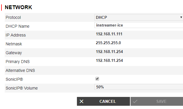
If you choose a static IP address following parameters should be set:
-
IP Address
-
Netmask
-
Gateway
Stream Configuration
Step 1
Go to "Stream" and click on "Edit".
Step 2
Define a "Stream Name". This name is only used for
internal identification.
Step 3
Define the "Stream Input" settings.
Input Channel: Choose "Mono Left" to select Input from the white connector, "Mono Right" for Input from the red connector, or "Stereo" for their combination.
Sampling Rate: Influences the quality of the captured data - a higher figure corresponds to a better quality.
Step 4
Define the "Stream Encoder" settings
Encoder Type: Select encoding format. The available formats are MP3 and AAC
Bitrate: Select the audio compression level using the 'Bitrate' field - higher is better.
Bitrate Type: Choose between CBR (constant bitrate) and VBR (variable bitrate).
Step 5
Define the "Server Type" setting.
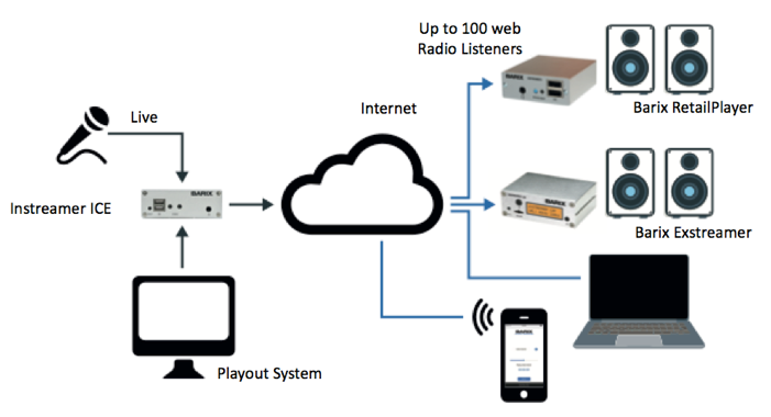
Choose "Icecast Server" to have the device act as an Icecast server that provides a stream for up to 100 listeners.
Choose "Icecast Source" to feed an external Icecast server.
Step 6
Define the "Stream Destinations" settings
Icecast Name: Define a name for your Icecast server or source (up to 32 characters)
Icecast Description: Define a description for your Icecast server or source (up to 32 characters)
Icecast Genre: Define the genre for your Icecast server or source (up to 32 characters)
Mount Point: Define the mount point of your server
Remote URL: Enter the URL address the stream will be sent to
Audio Port: Enter the port of the Icecast server used to give the listener(s) access to the stream
Username: Type in the stream username of the Icecast Server
Password: Type in the stream password of the Icecast Server. After configuring these fields, press OK to close the wizard. Changes will apply automatically.
Compliance and further Information
This equipment has been tested and found to comply with the limits for a Class B digital device, pursuant to part 15 of the FCC Rules. These limits are designed to provide reasonable protection against harmful interference in a residential installation. This equipment generates, uses and can radiate radio frequency energy and, if not installed and used in accordance with the instructions, may cause harmful interference to radio communications. However, there is no guarantee that interference will not occur in a particular installation. If this equipment does cause harmful interference to radio or television reception, which can be determined by turning the equipment off and on, the user is encouraged to try to correct the interference by one or more of the following measures:
-
Reorient or relocate the receiving antenna.
-
Increase the separation between the equipment and receiver.
-
Connect the device into an outlet on a circuit different from that to which the receiver is connected.
-
Consult the dealer or an experienced radio/TV technician for help.
Safety and precaution recommendations apply. Find them in the download section at www.barix.com

Find your distributor on this list for more hardware.
For questions that are extending the documentation, feel free to contact us on:
International: +41 434 33 22 22
USA: +1 866 815 0866
Email: support@barix.com
All information and the use of this product including all services are covered under the Barix Terms & Conditions and our Privacy Policy. Please follow the Safety and Precaution Recommendations. Barix is a ISO 9001:2015 certified company. All rights reserved. All information is subject to change without notice. All mentioned trademarks belong to their respective owners and are used for reference only.