Congratulation for buying the Barionet 1000.
Barionet 1000 is a fully programmable I/O device server, based on Linux/Lede/OpenWRT. The device features a wide range of interfaces such as two USB, WiFi, serial ports, Dallas 1-wire, analog and digital I/Os and Relays. It is IPv4 or IPv6 capable. Supporting multiple communication protocols, the Barionet device can be used in different applications such as automation, building control, public transport and many more. Barix Products are developed in Switzerland and manufactured to the highest standards.
We hope you find a quick start with this product. If you have any feedback or questions, write us at support@barix.com.
Safety Precautions
Please make sure to first read the safety information in order to avoid hazards.
Table of Contents
Package Content and Accessories
Package contents
-
Barionet 1000
-
2 Female Terminal blocks
-
Sticker with Wi-Fi and LAN MAC Address
Device functionality
Top view
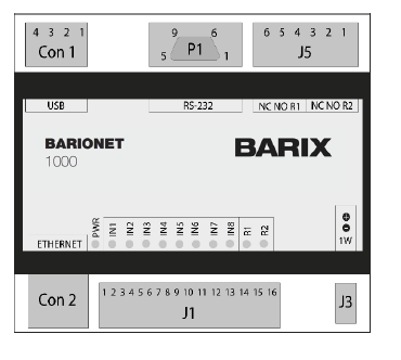
CON1 - 2xUSB Host
|
Pin |
Description |
|---|---|
|
1 |
VCC (+5V) |
|
2 |
D – (Data -) |
|
3 |
D + (Data +) |
|
4 |
GND |
J5 - Relay Outputs
|
Pin |
Description |
|---|---|
|
1 |
Relay 2 common |
|
2 |
Relay 2 normally open |
|
3 |
Relay 2 normally closed |
|
4 |
Relay 1 common |
|
5 |
Relay 1 normally open |
|
6 |
Relay 1 normally closed |
J1 - Digital Inputs, Digital Outputs, Power
|
Pin |
Description |
|---|---|
|
1..4 |
Input 1..4 Analog 0..15VDC or Digital |
|
5..8 |
Input 5..8 Digital |
|
9 |
Common Inputs Ground |
|
10..13 |
Output 1..4 Digital (Open Collector 0..24VDC, 300mA) |
|
14 |
Common Outputs Ground |
|
15 |
Power In +9..30VDC |
|
16 |
Power In - (GND) |
P1 - RS232 Serial Port
|
Pin |
Description |
|---|---|
|
2 |
RxD (Receive data) |
|
3 |
TxD (Transmit data) |
|
5 |
GND (Ground) |
|
7 |
RTS (Ready to send) |
|
8 |
CTS (Clear to send) |
|
1,4,6,9 |
NC |
CON2 - Ethernet (RJ45)
|
Pin |
Description |
|---|---|
|
1 |
TX + (Transmit data) |
|
2 |
TX - (Transmit data) |
|
3 |
RX + (Receive data) |
|
6 |
RX – (Receive data) |
|
4,5,7,8 |
NC |
J3 - Dallas 1-wire
|
Pin |
Description |
|---|---|
|
1 |
(DO NOT CONNECT) |
|
2 |
Ground (GND) |
|
3 |
1-wire data |
BLUE CPU LED shows Main CPU Status:
-
blinking: startup
-
solid: Main CPU running
GREEN Digital Input LEDs show Status of Digital Inputs
-
solid: Digital Input activated
RED Relais LEDs show Status of Relais Outputs
-
??? solid: Relais Output activated
Please Note: Digital Outputs do not have LED indication.
Hardware Installation
Slide the device upwards onto the DIN rail. Push it up and towards the rail until it snaps onto the upper rail edge. Before powering the device please read this quick install guide and mind the polarity of the power supply.
Connecting to power and initialization
Power Supply
The Barionet 1000 needs a DC supply voltage of 9V to 30V, 4W max. Please mind the polarity. When powered up, the Status LED of the CPU will start blinking, indicating that the device is starting up.
BLUE CPU LED: Main CPU
When the device is initialized, the Status LED turns solid.
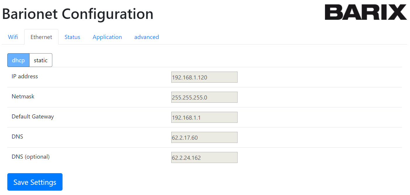
Connecting via Ethernet
Plug an Ethernet cable from the Barionet 1000 to an Ethernet network.
The Barionet 1000 is configured to be a DHCP Client by default. Use a Network Scanning Program or the Barix Discovery Tool in order to determine the IP Address according to the given MAC Address.
The Ethernet Interface can be configured using the Barix Web Interface. Use your Webbrowser in order to connect to the determined IP Address. The Root Password of the Device can be found on a sticker on the Backside of the Device. Use the "Ethernet" Section in order to configure the Ethernet Interface.
Connecting via Wi-Fi
Please note that the default Wi-Fi Interface is only turned on for the first 5 minutes after powering the device. Once a Wi-Fi is configured, the Wi-Fi Interface stays on.
The Wi-Fi Interface is turned on by default offering an SSID which is called “Barionet_” and the four last digits of its MAC address (for example, Barionet_0024B5). The security key/passphrase “barionet” is used to protect the WLAN.
Connect your PC to this Wi-Fi network. For this network, the Barionet works as a DHCP server and uses the IP Address 192.168.166.1 itself. For your PC, an IP address in the 192.168.166.x range will be assigned.
The Wif-Fi Interface can be configured using the Barix Web Interface. Use your Webbrowser in order to connect to the Device IP Address (192.168.166.1). The Root Password of the Device can be found on a sticker on the Backside of the Device. Use the "Wi-Fi" Section in order to configure the Ethernet Interface.
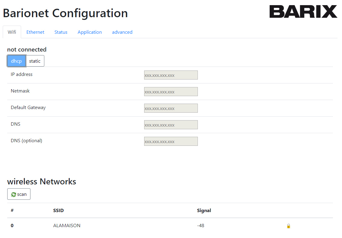
Leave your Wi-Fi IP address as DHCP or configure a Static IP. Use the "Scan" Button to search for available Wi-Fi Networks. Select one of the available networks and enter the Wi-Fi Access Key in order to connect.
For security reason, we recommend to turn off the WLAN interface if it is not needed in the Application. Use the LuCI Webinterface -> <Network> -> <Wireless> in order to turn the Interface off.
Resetting the Network Configuration
If you have entered a wrong Network configuration (Wi-Fi or Ethernet IP etc.), the Network configuration can be reset using the Factory Defaults Jumper (see Appendix). Set the Jumper for 3-5 Seconds and the Network Configuration is reset to factory defaults (Wi-Fi reset, Ethernet back on DHCP).
Setting Ethernet to Factory Testing IP
The Ethernet Interface can be set to the Factory Testing IP address 192.168.166.1 using the Factory Default Jumper (see Appendix). Set the Jumper for more then 20s (Blue LED will turn off) and the Ethernet IP Address will be set to static IP 192.168.166.1. Please note that this Setting is for configuration only, the Ethernet Configuration will be set back after a Reset if not otherwise configured.
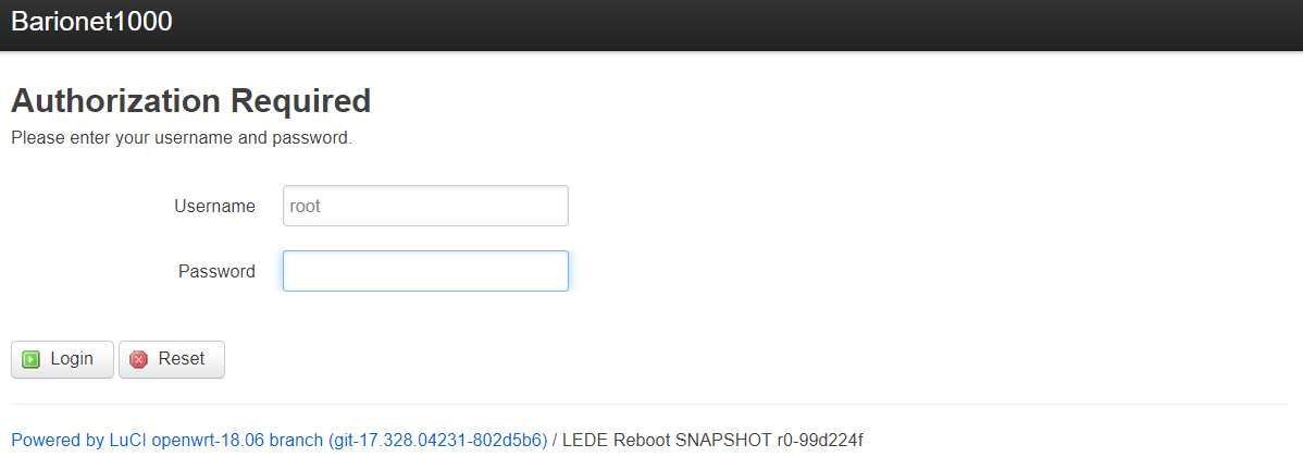
Changing Settings via Advanced Luci Web Interface
Opening the Advanced LuCi Interface
For advanced users the LuCI web interface can be accessed via the Barix Webinterface using the Advanced Section -> "LUCI config interface".
Login Data are the same as for the Barix Webinterface, the password for the Root user can be found on the sticker on the backside of the device.
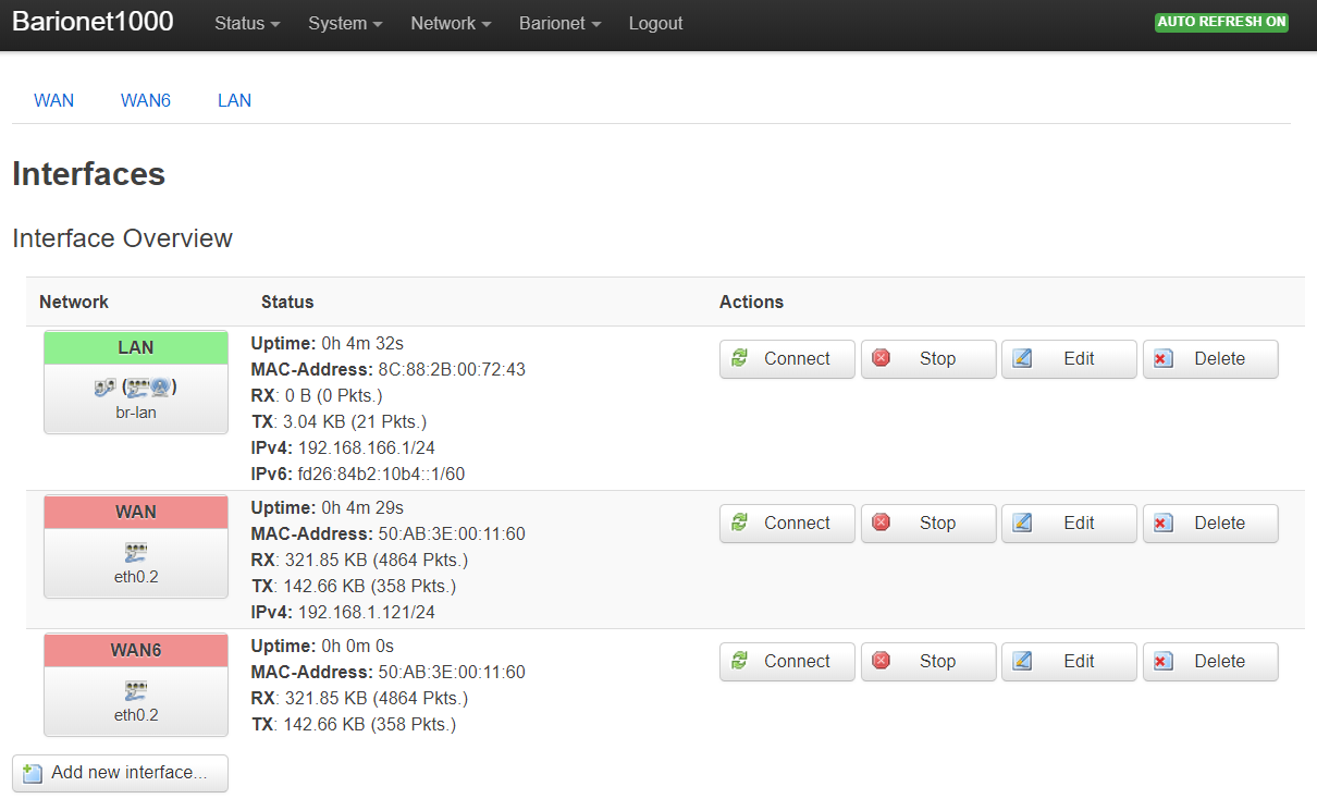
Changing Network Settings
In the LuCI web interface -> <Network> you will find all relevant settings, so you can set other IP addresses, enable/disable DHCP for each network port (Wi-Fi or Ethernet), and also enable the Wi-Fi interface.
Make sure you don’t lock yourself out if you change the settings !
Control IOs
In the LuCI web interface -> <Barionet> you will find a Control Interface to control and monitor the GPIOs of the Barionet.
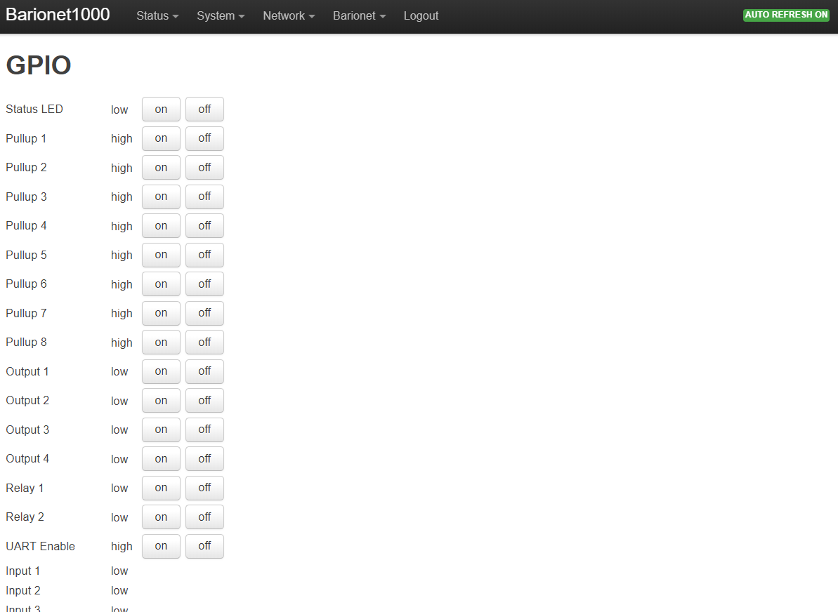
Simply click on the Control Buttons to change the state of Relays and IOs or see the Status of Digital Inputs.
Connecting via SSH
Use ssh or a similar client (for example, PuTTY, port 22, SSH option) and establish a connection as user “root” to the IP address of the Barionet (given DHCP Address if connecting via Ethernet or 192.168.166.1 if connected via Wi-Fi). The SSH root password is the same as used for the Webinterface which can be found on the sticker on the backside of the device.
Installing OpenWRT Packages
OpenWRT Packages can be installed by the standard OpenWRT/Lede Package installer by using “opkg” command
opkg list opkg list lists all the available packages
opkg list-installed lists the installed packages
opkg update updates the installed packages
opkg install <file> installes a specific package
Please note all custom installed packages will be deleted if a factory defaults or firmware update is applied.
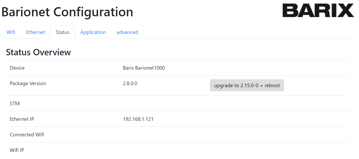
Updating the Barionet Application Packages (available from V2.15.0.0)
The Barionet Software is represented by different Packages in the Barionet Feed. In order to update the device to the newest Software without loosing any data, the Barionet Packages will need to be updated.
This Update can simply be done by the Webinterface.
IO Access from Scripts or programs
The IO ports are accessible through the standard OpenWrt IO device files.
The Device Files can be found in the folder /dev/gpio.
Relais Outputs
Relais Outputs: bio1 - bio4
Use the following shell command in order to control the relay outputs:
echo 1 > bio1/value set Relay 1
echo 0 > bio1/value reset Relay 1
Digital Outputs
Relais Outputs: bio101 - bio104
Use the following shell command in order to control the digital outputs:
echo 1 > bio101/value set Output 1
echo 0 > bio101/value reset Output1
Pullup Resistors
Pullup Resistors for the Digital Inputs: bio60101 - bio60108
Use the following shell command in order to control the pullup resistors:
echo 1 > bio60101/value turns Pullup Resistor for Input 1 on
echo 0 > bio60101/value turns Pullup Resistor for Input 1 off
Digital Inputs
Digital Inputs: bio201 - bio204
Use the following shell command in order to read the digital input value:
cat bio201/value reads Input 1
Analog Inputs
Analog Inputs: bio501 - bio504
Use the following shell command in order to read the analog input value:
cat bio501/value reads Analog Input 1
The device shows the reading on a 12bit resolution (0-4095)
Use of Serial Ports from scripts or programs
The Serial Port (RS232) is accessible through the standard OpenWrt USB device files.
The Device Files can be found in the folder /dev.
RS232 Interface: ttyS1
Use the following shell command in order to write to the Serial Port:
echo hello world > ttyS1 writes to RS232
Use the following shell command in order to read from the Serial Port:
cat ttyS1 reads from RS232
Please note that the default Baud Rate for the Serial Port is set to 9'600 Baud.
Use of 1-wire Temperature Sensors from scripts or programs
The 1-wire interface can be accessed using an OpenWrt device driver.
The Device Driver maps the 1-wire devices into the folder /sys/bus/w1/devices/.
Use the following shell command in order to read data from the 1-wire devices:
cat /sys/bus/w1/devices/yy-yyyy/w1_slave
Mounting a USB Stick
A USB Stick with FAT32 File System can be plugged into the USB port. In order to mount a USB stick to the OpenWRT File System the following command is used:
mount -t vfat /dev/sda1 /mnt/usb mounts the sda1 (first USB stick)
Note that “sda1” is eventually replaced by another interface. Use dmesg in order to determine the right interface.
Note that the /mnt/usb directory needs to be created before mounting.
Use of Modbus
The Barionet 1000 is supporting Modbus TCP Protocol in order to be controlled.
Modbus Interface: TCP Port 502
All IOs as well as a lot of more functions are accessible via Modbus IO Registers according to Appendix 1) IO Mapping.
Programming the Barionet in Lua
All the Devices in the Barionet Product Familiy can easy be programmed in Lua programming language. The important Lua packages in order to user IOs and Interfaces are pre-installed in the default Barionet Images.
Please use www.lua.org in order to get familiar with Lua and how it is programmed.
The Lua program will be loaded to the Barionet Device using SSH (see above). The program should be stored in /mnt/data/default.lua in order to be executed automatically after startup.
Persistent User Partition
The user partition (/mnt/data/) is the flash space which is persistent to firmware updates and factory defaults. All custom developments will need to be done in the User Partition in order to be on the device after a firmware update or a factory defaults.
Reboot the Device
With Advanced LuCI Web Interface
On the Advanced LuCI web interface go to the System -> <Reboot>
Select “Perform Reboot”.
Reset to factory defaults
With Advanced LuCI Web Interface
On the Advanced LuCI web interface go to <System> -> <Backup/Flash Firmware>
Under Backup/Restore select “Reset to defaults” and perform the factory reset.
At this point, the device will reboot and apply default settings.
Please note that all data except the User Partition will be deleted. Barionet Application Package will be set back to Firmware Image default.
By Hardware Jumper
The Factory defaults can also be set by the Factory Defaults Jumper (see Appendix). Set the Jumper for at least 10s to perform factory Defaults.
At this point, the device will reboot and apply default settings.
Please note that all data except the User Partition will be deleted. Barionet Application Package will be set back to Firmware Image default.
Upload Firmware Image
For a complete update of the Device, the OpenWRT/LEDE Firmware image is provided by Barix at www.barix.com/downloads .
The easiest way is to upload the Firmware Image is using the Advanced LuCI Webinterface: <System> -> <Backup / Flash Firmware>.
Make sure the “Keep Settings” option is selected, if you want to keep your settings and your Data Files. If "Keep Settings" is not selected, the update procedure ensures that the Device is correctly set back to Factory Defaults after the Firmware Update.
Be patient during the Software update and do not disconnect the Power Supply. The Software Update can Take up to 10 Minutes.
Please note that all data except the User Partition will be deleted.
If other Operating System Data will need to be kept (e.g. custom installed packages etc), only the Barionet related Packages, but not the complete firmware will need to be updated. see more about this above -> "Updating the Barionet Packages".
Reset, Factory Defaults and Update Scenarios
The following table gives an overview about the above described Reset, Factory Defaults and Update Scenarios.
|
Action |
Description |
OpenWRT/LEDE OS |
Barionet Application
|
Network Configuration |
Custom Packages |
User Partition |
|---|---|---|---|---|---|---|
|
Reset |
Device Restarts |
remain |
remain |
REMAIN |
REMAIN |
REMAIN |
|
Network Factory Defaults (Jumper 3-5 Seconds) |
Sets the Network configuration back to factory Defaults |
REMAIN |
REMAIN |
Reset |
REMAIN |
REMAIN |
|
Standard Factory Defaults (Jumper >10s or WebUI) |
Sets Device back to factory Defaults |
REMAIN |
reset |
reset |
reset |
REMAIN |
|
Update Barionet Package |
Updates the related Barionet Application Packages |
REMAIN |
update |
REMAIN |
REMAIN |
REMAIN |
|
Upload Firmware Image (with "keep settings") |
Updates the complete OS Image but keeps the Settings |
update |
update |
REMAIN |
reset |
REMAIN |
|
Upload Firmware Image (without "keep settings") |
Updates the complete OS Image and resets the Settings to factory Defaults |
update |
update |
reset |
reset |
REMAIN |
Appendix
IO Mapping
|
IO Addr |
Read/Write |
Size |
Description |
Driver Alias |
Driver Link |
|---|---|---|---|---|---|
|
1 |
R / W |
1 bit |
Relay 1 |
rel1 |
bio1 |
|
2 |
R / W |
1 bit |
Relay 2 |
rel2 |
bio2 |
|
10..100 |
R / W |
1 bit |
Virtual IO Bits |
|
|
|
101 |
R / W |
1 bit |
Digital Output 1 |
out1 |
bio101 |
|
102 |
R / W |
1 bit |
Digital Output 2 |
out2 |
bio102 |
|
103 |
R / W |
1 bit |
Digital Output 3 |
out3 |
bio103 |
|
104 |
R / W |
1 bit |
Digital Output 4 |
out4 |
bio104 |
|
105..200 |
R / W |
1 bit |
Virtual IO Bits |
|
|
|
201 |
R only |
1 bit |
Digital Input 1 |
in1 |
bio201 |
|
202 |
R only |
1 bit |
Digital Input 2 |
in2 |
bio202 |
|
203 |
R only |
1 bit |
Digital Input 3 |
in3 |
bio203 |
|
204 |
R only |
1 bit |
Digital Input 4 |
in4 |
bio204 |
|
205 |
R only |
1 bit |
Digital Input 5 |
in5 |
bio205 |
|
206 |
R only |
1 bit |
Digital Input 6 |
in6 |
bio206 |
|
207 |
R only |
1 bit |
Digital Input 7 |
in7 |
bio207 |
|
208 |
R only |
1 bit |
Digital Input 8 |
in8 |
bio208 |
|
209..400 |
R / W |
1 bit |
Virtual IO Bits |
|
|
|
501 |
R only |
12 bits |
Analog Input 1 Value |
analog1 |
bio501 |
|
502 |
R only |
12 bits |
Analog Input 2 Value |
analog2 |
bio502 |
|
503 |
R only |
12 bits |
Analog Input 3 Value |
analog3 |
bio503 |
|
504 |
R only |
12 bits |
Analog Input 4 Value |
analog4 |
bio504 |
|
505..600 |
R / W |
16 bits |
Virtual IO Registers |
|
|
|
701..1000 |
R / W |
16 bits |
Virtual IO Registers |
|
|
|
60101 |
R / W |
1 bit |
Pull-Up Digital Input 1 |
pullup1 |
bio60101 |
|
60102 |
R / W |
1 bit |
Pull-Up Digital Input 2 |
pullup2 |
bio60102 |
|
60103 |
R / W |
1 bit |
Pull-Up Digital Input 3 |
pullup3 |
bio60103 |
|
60104 |
R / W |
1 bit |
Pull-Up Digital Input 4 |
pullup4 |
bio60104 |
|
60105 |
R / W |
1 bit |
Pull-Up Digital Input 5 |
pullup5 |
bio60105 |
|
60106 |
R / W |
1 bit |
Pull-Up Digital Input 6 |
pullup6 |
bio60106 |
|
60107 |
R / W |
1 bit |
Pull-Up Digital Input 7 |
pullup7 |
bio60107 |
|
60108 |
R / W |
1 bit |
Pull-Up Digital Input 8 |
pullup8 |
bio60108 |
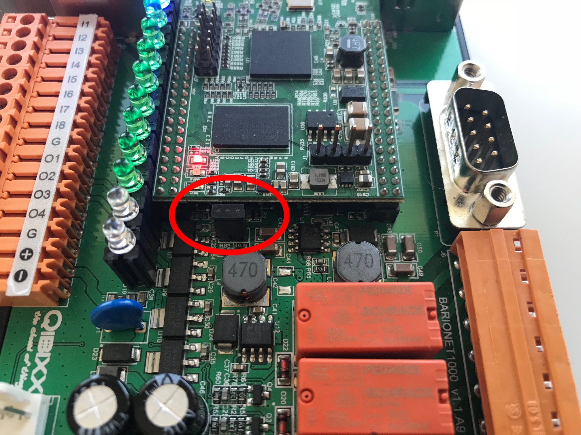
Access to the Factory Reset Jumper
The Factory Reset Jumper can be accessed under the Cover of the Barionet 1000. Use a screw driver to unlatch the Top Case Part in order to open the case.
Compliance and further Information
This equipment has been tested and found to comply with the limits for a Class B digital device, pursuant to part 15 of the FCC Rules. These limits are designed to provide reasonable protection against harmful interference in a residential installation. This equipment generates, uses and can radiate radio frequency energy and, if not installed and used in accordance with the instructions, may cause harmful interference to radio communications. However, there is no guarantee that interference will not occur in a particular installation. If this equipment does cause harmful interference to radio or television reception, which can be determined by turning the equipment off and on, the user is encouraged to try to correct the interference by one or more of the following measures:
-
Reorient or relocate the receiving antenna.
-
Increase the separation between the equipment and receiver.
-
Connect the device into an outlet on a circuit different from that to which the receiver is connected.
-
Consult the dealer or an experienced radio/TV technician for help.
Safety and precaution recommendations apply. Find them in the download section at www.barix.com

Find your distributor on this list for more hardware.
For questions that are extending the documentation, feel free to contact us on:
International: +41 434 33 22 22
USA: +1 866 815 0866
Email: support@barix.com
All information and the use of this product including all services are covered under the Barix Terms & Conditions and our Privacy Policy. Please follow the Safety and Precaution Recommendations. Barix is a ISO 9001:2015 certified company. All rights reserved. All information is subject to change without notice. All mentioned trademarks belong to their respective owners and are used for reference only.