The scope of this document is to give a thorough introduction on the Annuncicom YA404 Analog Head-End. At the end of this guide the user will be able to run a basic setup and have an audio stream playing.
The Annuncicom AHE-YA404 is a powerful all-in-one Analog Head End solution designed to modernize legacy 2- or 4-wire intercom and paging systems—without the need to replace existing cabling or call stations. With integrated VoIP SIP support and onboard amplification, the AHE-YA404 enables seamless paging and intercom functionality from standard SIP phones to up to 16 individual 2 or 4 wire intercom panels.
Annuncicom Analog Head-End runs the IP Audio Client software. Refer to the IP Audio Client user manual for a complete explanation on the software functionalities.
Package Content
-
Analog Head-End device (including screw terminal blocks)
-
Quick Install Guide
The Barix Annuncicom Analog Head-End is an audio over IP Intercom solution, offering a multitude of interfaces:
-
1x 10/100 MB Ethernet
-
1x 24VDC power input
-
(16x) 4-wire interfaces with speaker/mic and dry contact closure:
-
Speaker out Paging: 25V/70V constant voltage with max. 50W power output
-
Speaker out Intercom: 2.5W power output (only 1 station at a time can be in Intercom mode)
NOTE: The speaker / mic functionality is vox-controlled by the call center side (monitoring station)
-
-
2x USB Type A
Hardware functionality
|

|
Rear View

|
||
|
LEDs |
Intercom Station’s LEDs (see Station LED chapter for more details) |
RESET button |
Short press while powered (1s - 9s) → Reboots the device Long press while powered (10s - 15s) → Hard reset to defaults (including network settings) Press and hold for 8s while powering up → Rescue process triggered: device will connect to the Barix update server and install the latest firmware |
|
Intercom Stations |
(16x) 4pin screw terminal block. Each station offers the following connections, from left to right:
|
10/100 ETH |
Fast Ethernet network connection on RJ45 |
|
|
|
EXT Port |
(2x) EXT ports for USB connections |
|
|
|
Power |
2.1mm barrel connector for 24VDC power input
Use a 24VDC / 3A
|
Audio Architecture
The Analog Head End device employs a “dual-purpose”, paging and intercom, audio architecture designed to provide seamless communication between stations and central control. Understanding this architecture is essential for proper system operation and configuration.
Channel Overview
The system operates using two distinct audio channels, each serving specific communication functions:
1. Paging Channel
The Paging Channel serves as the default audio output for all stations when no active SIP intercom calls are in progress. This channel continuously broadcasts audio content configured through the SOURCE tab in the web interface. Common applications include background music, announcements, or ambient audio distribution to all connected stations.
2. Intercom Channel
The Intercom Channel activates when a station initiates communication with the central station. This channel takes priority over the Paging Channel and is configured through the Intercom tab in the web interface. The system supports a maximum of one station on the intercom channel at any given time.
Intercom Operation Characteristics
Audio Direction Control
When a station is connected via the intercom channel, audio transmission operates in half-duplex mode. The direction of audio flow is automatically determined by audio presence detection at the central station:
-
Station-to-Central: When no audio is detected from the central station, the station's speaker functions as a microphone, transmitting room audio to the central station.
-
Central-to-Station: When audio is detected from the central station, it takes priority and is transmitted to the station's speaker.
Dynamic Role Switching
The station's speaker unit dynamically switches between output (speaker) and input (microphone) modes based on the communication direction, enabling natural two-way conversation flow.
Typical Operation Workflow
Standard Operation Sequence
-
Default State: All stations receive audio from the Paging Channel (e.g., background music or announcements).
-
Call Initiation: A user activates the station's input mechanism to initiate communication with the central station.
-
SIP Call Establishment: The system establishes a SIP call between the requesting station and the designated central extension.
-
Initial Communication Phase:
-
The central station is initially muted upon call connection
-
The station's speaker operates as a microphone, transmitting room audio to the central station
-
Central personnel can hear audio from the requesting station's location
-
-
Bidirectional Communication:
-
When central station personnel speak, the station's speaker returns to output mode
-
Audio from the central station is transmitted to the requesting station
-
Communication continues with automatic direction switching based on audio presence
-
-
Call Termination: Upon call completion, the station automatically returns to receiving audio from the Paging Channel.
Configuration Requirements
-
Paging Channel: Configure audio sources through the SOURCE tab in the web interface
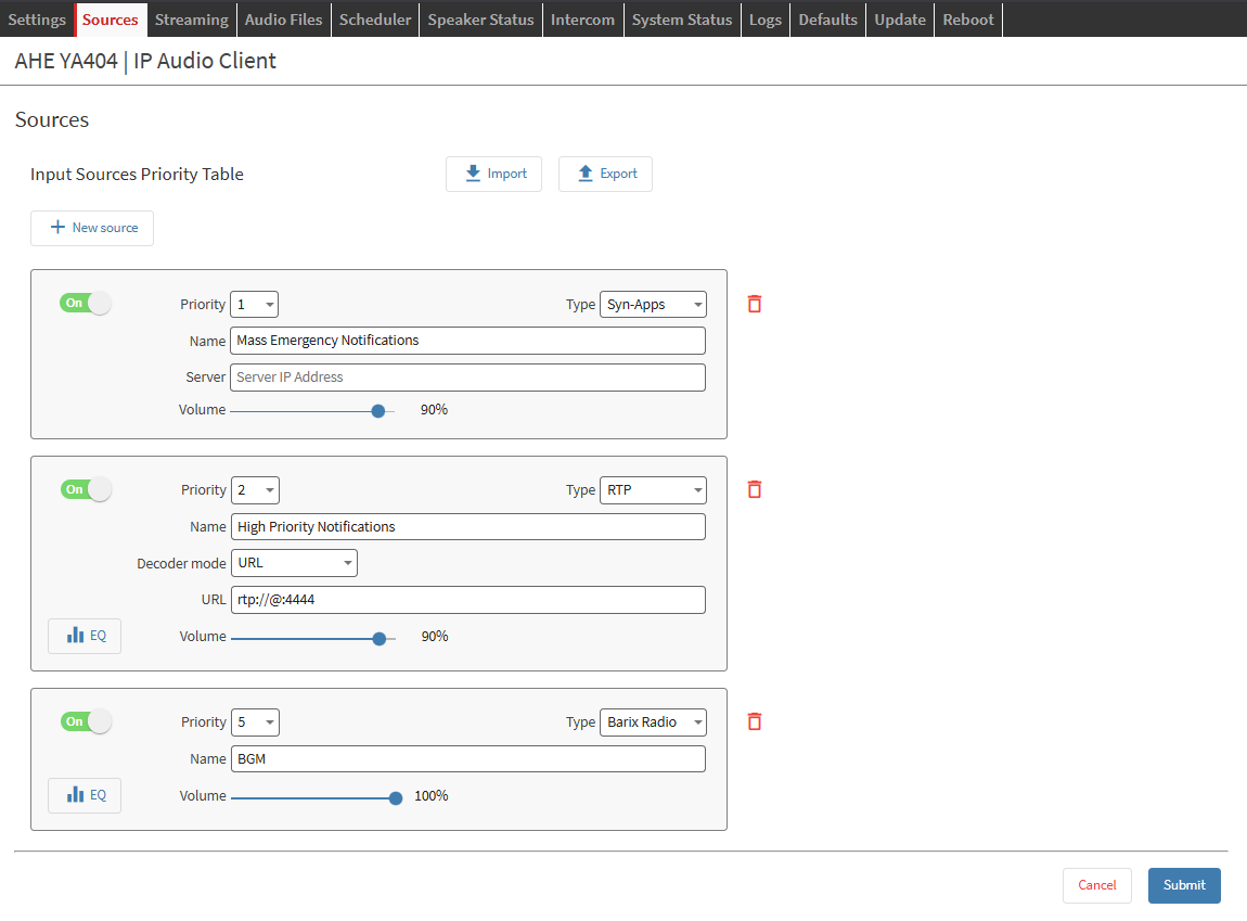
SOURCE TAB Controls the Paging Channel Output
-
Intercom Channel: Configure communication parameters through the Intercom tab in the web interface. Each station requires a SIP Extension within the SIP Server used.
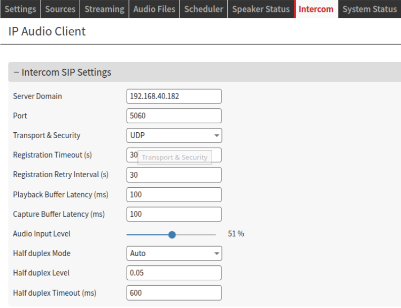
INTERCOM Tab controls the SIP settings for each station
Group Paging
By configuring a SIP Source in the SOURCES tab it will be possible to use a dedicated extension for an ALL station page.
When doing so, the channel used is the paging channel which drives ALL stations with the same signal.
It is NOT possible to perform a group page for a subset number of stations.
Station’s LED behavior
The following table will show the LED behavior depending on the application state considering a multitude of factors, including sources playing / not playing on each station.
|
LED State |
Meaning |
|---|---|
|
OFF |
Intercom SIP account not registered or configured, no RTP / HTTP / SIP source playing |
|
OFF / BLUE (*) 🔵 |
Intercom SIP account not registered, playing RTP / HTTP source |
|
OFF / PURPLE (*) 🟣 |
Intercom SIP account not registered, playing SIP Source on ALL Stations |
|
GREEN 🟢 |
Intercom SIP account registered, idle (no RTP / HTTP / SIP sources playing) |
|
🟢 GREEN / BLUE (*) 🔵 |
Intercom SIP account registered, playing RTP / HTTP source |
|
🟢 GREEN / PURPLE (*) 🟣 |
Intercom SIP account registered, playing SIP Source on ALL Stations |
|
WHITE |
Intercom call button pressed |
|
RED (1 sec) 🔴 |
Intercom call denied (another call in progress) |
|
YELLOW 🟡 |
Intercom in active call - audio direction: station → central |
|
YELLOW (blink) 🟡 |
Intercom in active call - audio direction: central → station |
(*) x/y means blinking at a lower rate, like 500ms for x and 500ms for y - for example “OFF for 500ms - Blue for 500ms”.
Installation
STEP 1 Connect the Audio Equipment
The Annuncicom Analog Head-End provides intercom panel connections with 4 wires: speaker (+/-) and contact closure (input - gnd). Wire at least 1 intercom panel before moving to step 2.
The speaker output is 25V/70V constant voltage output
STEP 2 Connect the network
Connect your Annuncicom Analog Head-End to the network using a standard Ethernet cable (CAT5e or better). The device needs a DHCP server in the same network to acquire an IP address for the first time.
STEP 3 Power up
Use a 24VDC/3A power supply to power up the device. At boot the device will
-
Light up all the LEDs of everu station
-
15s after power up → Device announces its IP Address (take note to be able to enter the web interface later)
-
35s after power up → Application is ready → Station LEDs turn off (by default configuration) and the operation LEDs are steady green.
Annuncicom Analog Head-End is ready to be used.
First Configuration - Play Barix Radio
|
1 |
From a PC in the same network subnet of the device, use a web browser to access the web interface by typing the IP Address into your browser (the one noted during boot) |
|
2 |
Login is required, by default user is "admin" and the password is provided on the sticker on the backside of the device (PW label) 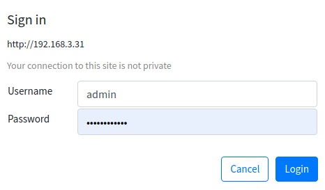
|
|
3 |
Navigate to the Source page - by default the application runs InformaCast (if licensed) and SynApps. 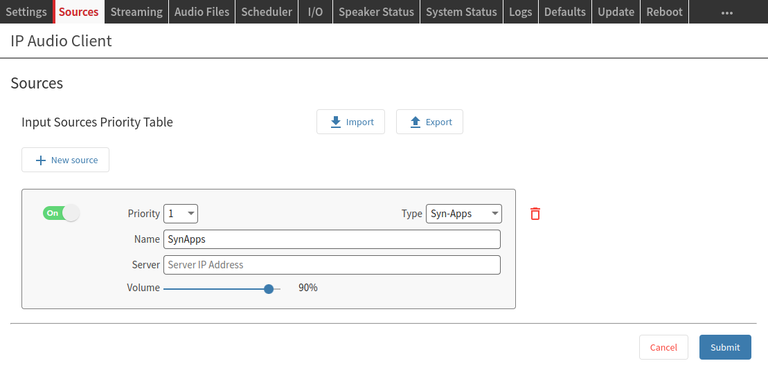
|
|
4 |
Select Barix Radio from the Type drop-down menu. Barix Radio is a source type pre-configured to play music from https://www.barix.com/radio.m3u - Change the source Name into “Barix Radio” (not mandatory) |
|
5 |
Click on SUBMIT → After few seconds music will play |
|
6 |
Check out the Speaker Status page to monitor the playback. When the source plays the corresponding layer turns green. Barix Radio now is playing on ALL the stations. 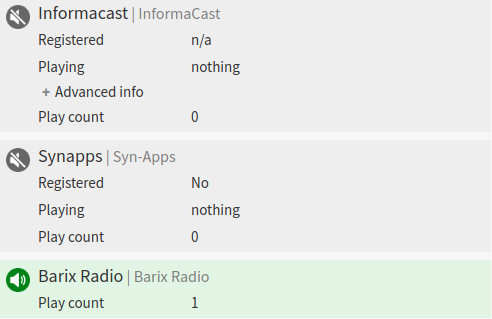
|
|
7 |
Locate the Intercom tab and setup the INTERCOM SIP SETTINGS - This will be the server used by each station’s extension 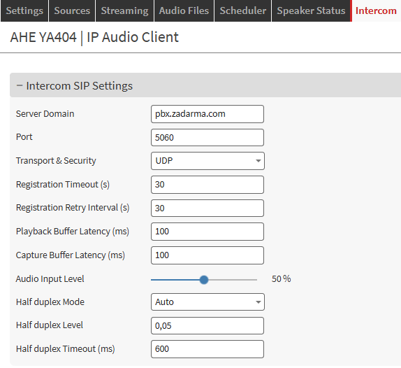
|
|
8 |
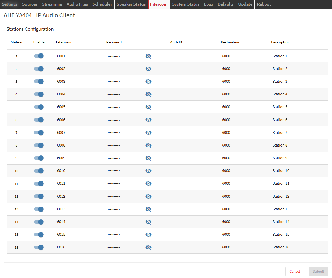
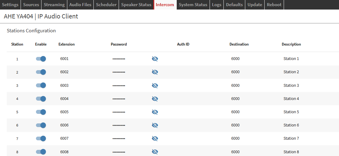
Setup the SIP extensions to be used by every station.
|
|
9 |
Close a station input, this will trigger a call to the central for that station which will stop playing BGM until the intercom call is in progress.
|
For more details on IP Audio Client, the software running on the Annuncicom Analog Head-End consult the IP Audio Client user manual.
Compliance and further Information
This equipment has been tested and found to comply with the limits for a Class B digital device, pursuant to part 15 of the FCC Rules. These limits are designed to provide reasonable protection against harmful interference in a residential installation. This equipment generates, uses and can radiate radio frequency energy and, if not installed and used in accordance with the instructions, may cause harmful interference to radio communications. However, there is no guarantee that interference will not occur in a particular installation. If this equipment does cause harmful interference to radio or television reception, which can be determined by turning the equipment off and on, the user is encouraged to try to correct the interference by one or more of the following measures:
-
Reorient or relocate the receiving antenna.
-
Increase the separation between the equipment and receiver.
-
Connect the device into an outlet on a circuit different from that to which the receiver is connected.
-
Consult the dealer or an experienced radio/TV technician for help.
Safety and precaution recommendations apply. Find them in the download section at www.barix.com

Find your distributor on this list for more hardware.
For questions that are extending the documentation, feel free to contact us on:
International: +41 434 33 22 22
USA: +1 866 815 0866
Email: support@barix.com
All information and the use of this product including all services are covered under the Barix Terms & Conditions and our Privacy Policy. Please follow the Safety and Precaution Recommendations. Barix is a ISO 9001:2015 certified company. All rights reserved. All information is subject to change without notice. All mentioned trademarks belong to their respective owners and are used for reference only.