User Manual
Document Name: | Application User Manual |
|---|---|
Document Date: | 11. Sep. 2019 |
Document Version: | 1.00 |
Product Name / Version | SIP OPUS CODEC / V1.3.1 |
DOCUMENT REVISION TABLE
Date | Version | Who | Change |
|---|---|---|---|
11-12/09/2019 | 1.0 | ASI | Created the first version of the document |
13/09/2019 | 1.1 | ASI | Added info about using the CGI commands |
1 Introduction
1.1 About “SIP OPUS CODEC”
SIP OPUS CODEC Application FW is the Linux ARM platform successor of Barix ABCL SIP Client FW. It has been developed using the PJSUA2 library from the PJSIP project.
While it is not providing 100% feature compatibility with the previous SIP solution, the SIP OPUS Codec FW offers some important advantages:
Full implementation of the RFC-3261 standard;
Better performance thanks to the powerful embedded ARM core;
Support for Speex, iLBC, OPUS codecs;
Configurable state-of-the-art AEC implementation;
Configurable SNMP control;
1.2 Features
Being based on the PJSIP stack, the SIP OPUS CODEC solution inherits all features supported by the PJSIP stack implementation. However, the Barix implementation does not provide user interface for configuring all of them. Here is a short non-exhaustive list of the supported features.
General Features
SIP (RFC 3261) compliant architecture
Configurable destination number to call on input contact
Configurable “call/close on level” feature
Configurable “peer to peer” or “proxy based” connections
Configurable SIP and audio RTP ports
Support for G.711, G.722, Speex, iLBC and OPUS codecs
DTMF door open key sequence
Transparent bidirectional Serial-To-TCP gateway
Friendly profile based WEB configuration UI
10/100 Mbit Ethernet connection with automatic network configuration (BOOTP, DHCP), and as well as manual static IP configuration;
Syslog debugging messages
SIP features
Peer to peer session, device can connect directly to the final UAS trough INVITE, and act as UAS on incoming calls
Transaction through a intranet or Internet UAS, device can register to an outbound Registrar, and establish dialogs through an outbound Proxy
UAC supported methods: REGISTER, INVITE, CANCEL, BYE, ACK,OPTIONS,INFO
Supported status messages: 200, 180, 603
NAT detection (RFC 5768)
Transport (TCP/UDP), currently hardcoded to UDP only
Media Capabilities
DTMF (RFC-4733,2833)
echo cancellation (WebRTC, Speex, suppressor, or native)
inband DTMF/tone generation
Audio Codecs:
◦ Speex 8KHz, 16Khz, 32KHz
◦ iLBC, GSM,
◦ L16, G.711A/U (PCMA/PCMU),
◦ G.722,
◦ G.722.1 16KHz/32KHz
◦ Opus Codec
ALSA support
1.3 Supported hardware
The SIP OPUS CODEC solution is designed to run on the following Barix devices:
MA400 – as full duplex mono codec
M400 – as stereo decoder only/encoder only
1.4 Additional documents
Technical specifications for the supported devices can be found in the corresponding product sheet which can be downloaded from Barix site www.barix.com.
The SIP OPUS client has been developed using the PJSIP stack v2.8. For detailed technical information about the supported SIP features please refer to the PJSIP web page.
1.5 About this manual
Links to chapters
References to chapters (e.g. X Chapter name) are red and underlined and serve as direct links when viewed in Adobe Acrobat Viewer. Click on the link to jump to the referenced chapter, click on the left arrow icon to jump back to where you came from.
Bookmarks pane in Adobe Acrobat
The complete “Table of Contents” is available in Adobe Acrobat Viewer. Click on the “Bookmarks” pane tab on the left side of Adobe Acrobat Viewer to open it. Click on any bookmark to directly jump to the corresponding part of the manual.
Chapter overview
This manual is divided into the following chapters:
Chapter System requirements describing some basic SIP environment and system configurations.
Chapter Quick Start Guide explaining how to quickly set up the device for use with the SIP client.
Chapter Advanced WEB UI configuration giving a detailed guide for the WEB UI SIP OPUS CODEC configuration.
Chapter Extra features in the SIP OPUS CODEC application describing in details how to use some of the advanced features provided by the application.
Chapter Common Issues and Useful Tips explaining how to solve the most common issues to have the application working.
2 System requirements
2.1 SIP environment
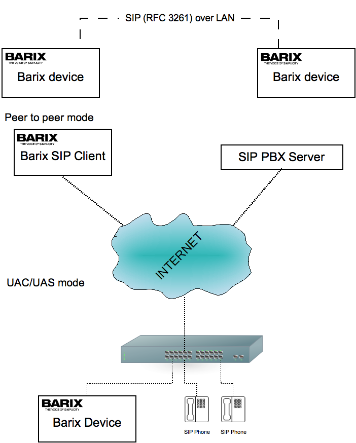
The SIP OPUS CODEC application can run through a 10/100 Mbit Network, as a peer to peer application, or as a standard SIP “user agent client/server” (UAC/UAS) in a PBX environment.
2.2 SIP server compatibility
The SIP OPUS CODEC application has been tested with the following list of SIP Registrar Server/PBX:
Asterisk
Elastix
SipXecs
FreePBX-13
OpenSER
FreeSWITCH
The following SIP servers have been confirmed to work by our partners:
ONSIP
Interoperability with other SIP servers might work, but is not tested.
3 Quick Start Guide
This chapter explains how to do the initial setup of the SIP OPUS CODEC Applications.
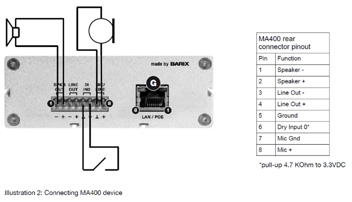
3.1 Connecting MA400 device
The MA400 device is shipped with 8 pin female Molex screw terminal plug that is to be plugged in the yellow socket at the back panel of the device. Connect all the needed wires to it, then insert it into the male Molex socket:
STEP 1
Connect the wires of your 8 Ohm 5W speaker to terminals 1 and 2 of the Molex plug. If needed, connect also the Line In wires of your audio equipment (for example external amplifier) to terminals 3 and 4 of the Molex plug as well.
STEP 2
Connect your push button to terminals 5 and 6 of the Molex plug
STEP 3
Connect the Microphone wires to terminals 7 and 8 of the Molex plug
STEP 4
Last, connect one end of the LAN cable to the LAN/POE connector of the MA400 device, and the other end to your POE network switch.
If you do not have a POE switch, then plug the LAN cable to the POE powered output of a POE injector, and the LAN input of the injector to your network switch or router. Last, power on the POE injector.
Now the MA400 device shall start booting, and announce its IP address on the speaker or the headphone output. At the end of the boot process, LED1 shall be steady green, while LED2 shall be off.
3.2 Connecting the M400 Device
STEP 1
Plug a standard (straight) network cable into the LAN port of the M400, and the other end into your switch connected to your LAN.
STEP 2
If you plan to use the M400 device as DECODER, then connect the RCA Line In of your audio equipment (for example audio amplifier with RCA input) to the RCA (Cinch) connectors of the M400 device.
If using it as ENCODER, then connect the Line Out of your audio equipment (for example CD player, or microphone preamplifier with RCA input) to the RCA (Cinch) connectors of the M400 device.
STEP 3
Last, connect the power supply adapter to the 5V power port of the device. The device will start booting. At the end of the boot process, LED1 shall be steady green, while LED2 shall be off.
3.3 Basic configuration of the PJSUA client
Once the device is powered up, it will try to get automatically IP address using DHCP, and announce it on the speaker or headphone output. After boot, open the device web page with your favourite browser. You will see the empty home page of the SIP Client, which is the default application:
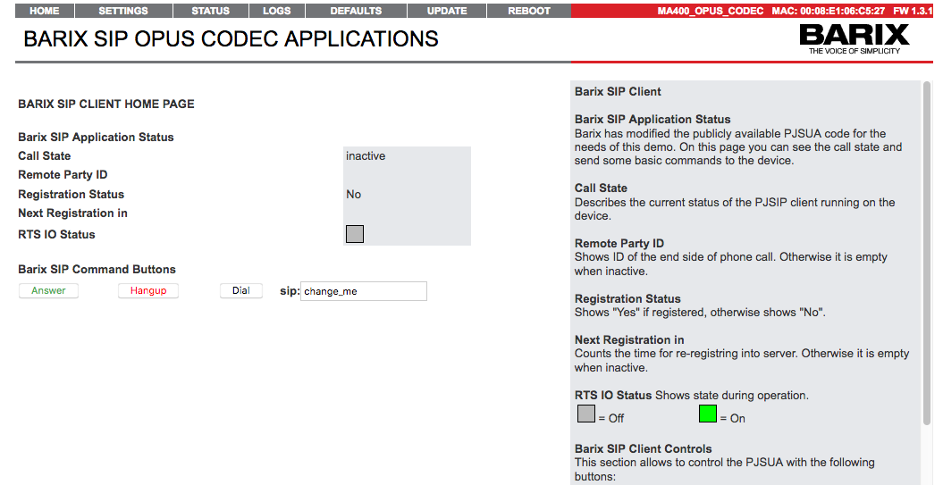
Illustration 3: Home page of un-configured SIP client
The registration status is showing “No”, because the device is not yet configured.
Next, please click on the “SETTINGS” tab from the navigation menu. The Basic configuration menu page will show up.
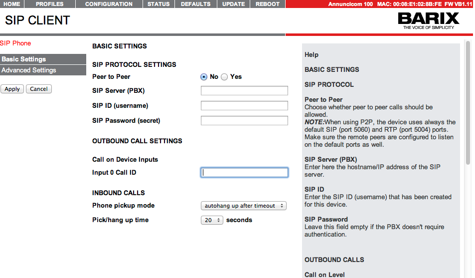
Illustration 4: SIP client Basic Settings menu page
Here you will find the most essential settings that need to be configured for the SIP client to be successfully started. Please contact your network administrator to provide you with the login data for your SIP account, and type them in the corresponding fields.
Setting Name | Purpose | Example value |
|---|---|---|
Server Name (PBX) | The URL or the IP address of your SIP server. The IP be a public (WAN), or private (LAN) IP address. In the example a local FreePBX SIP server is used | 192.168.11.107 or mysip.example-sip.com (replace with the real DNS name of your SIP server) |
SIP ID (username) | The username used to register on the SIP server | 1000 |
SIP password (secret) | The password for your SIP account | your_own_password (not displayed while typing) |
Auth User Name | Some SIP servers have additional authentication name for better security. If given by your SIP provider, enter it here. | empty |
Click the “Apply” button, and wait the SIP client to be restarted. If the SIP account settings are correct, the device should register (status set to “Yes”), and LED2 on the front panel of the device shall be steady green.
Next step is to configure the “Call On Input ID” to be able to initiate calls on a button press. Open again the web page of the device, and go to SETTINGS-→Advanced Setting-→SIP Account. Type the SIP ID of the remote peer in the “Call On Input ID” field, then click “Apply” to save the settings.
NOTE: The call ID must be in the format sip_id@sip_server.ip, ex.: 1001@192.168.11.107
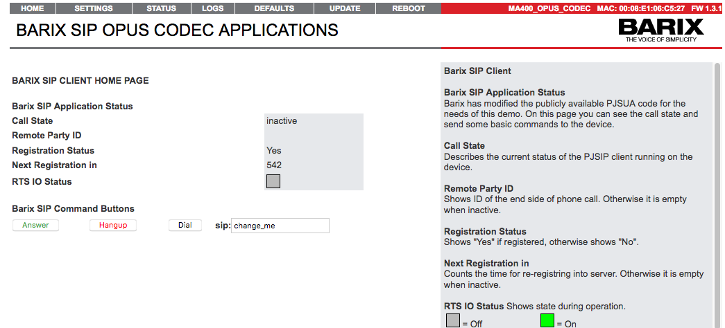
Illustration 5: Home page of a configured and registered SIP client
Now the SIP client is ready to make and receive calls. Press the button, or click “Dial” to call to ID 1000[1]. The SIP client will start ringing, and a call status “ringing” with “Remote party ID: 1001@192.168.11.107” will be displayed on the SIP client home page. When the call is answered, an “active” call status shall be displayed.
Make sure that ID 1001 is existing and registered to the same SIP server. This could be another BARIX SIP client, or any HW or SW SIP phone.
4 Advanced WEB UI configuration
4.1 Home page
After powering up, the Barix device WEB page is reachable at its IP address. Open your preferred Internet browser, and connect to the device by writing the IP address in the browser URL bar. A menu with a navigation bar and the device home page pre-loaded will show up.
The Home page displays the most essential configuration and status information grouped in the following sections:
BARIX SIP CLIENT HOME PAGE
Barix SIP Application Status
Time till next Registration
Shows the remaining time till the next registration attempt.
Call State
Shows the current call state, and may take one of the following values:
inactive:
No audio stream is received, and the SIP client is accepting calls;
ringing:
The SIP client has received an INVITE message, or has initiated an outgoing call, and is
ringing. The ID of the remote party is also displayed;
active:
The SIP client is in a call session with the displayed remote party.
Registration Status
Shows “YES: if registered, “No” otherwise.
Time till next Registration
Shows the remaining time till the next registration attempt.
RTS I/O Status
This section is displays the status of the RTS output, that is available on the MA400 devices. The following states are available:
Output high (relay activated) | Output low (relay not active) |
NOTE: You cannot attach a relay directly to the RTS pin, you need to control it via a transistor.
Barix SIP Command Buttons
Shows a panel with the following buttons:
Answer:
Click this button to answer incoming call
Hangup:
Click this button to close active or cancel outgoing call
Dial:
Click this button to dial the configured remote peer ID. You can also edit the remote peer ID, and then click the button to dial.
NOTE: When dialing using the digital button (on MA-400 devices only), then the stored ID is used. Changing the ID here does not update it in the stored settings.
4.2 Configuration Page
The configuration page consists of three frames - the menu navigation section, the settings section, and the help section.
The menu navigation section contains two menus - Basic and Advanced. While the Basic menu shows only the most essential settings needed to initially configure the application, the Advanced menu gives access to all settings available for the selected application.
Clicking on the selected menu options shows the configuration options, and their relevant help page. After configuring the needed options, click the “Apply” button to save the changes.
NOTE: Settings are not preserved if you switch between the Basic and Advanced menus. Make sure you apply the changes you have already done before switching to the other menu!
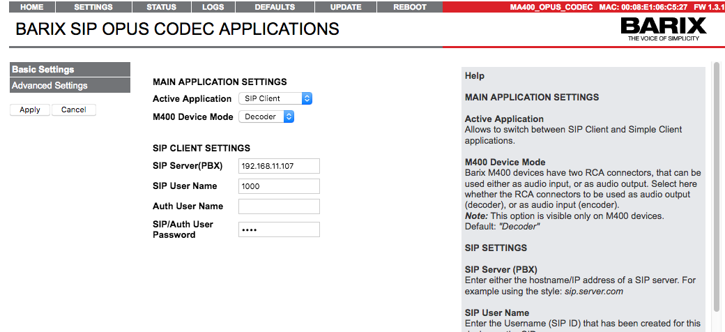
Illustration 6: SIP Client Configuration page
Below is the full list of configuration options available in the Advanced menu.
SIP ACCOUNT SETTINGS
SIP Server (PBX)
Enter the hostname or the IP address of a SIP server.
SIP User Name
Enter the SIP ID (username) that has been created for this device on the SIP server.
Auth User Name
Enter the Authentication ID given by your SIP provider to use for authentication (if it is different than the SIP ID). Most often you do not need to fill in anything, just leave it empty to use only the SIP ID for authentication.
SIP/Auth User Password
Enter here the password given by your SIP provider. Leave this field empty if the PBX doesn't require authentication.
Outbound Proxy
Some SIP servers can be used only via a proxy. Enter here the IP address, or the proxy URL given by your SIP provider.
Listen RTP Port
Listening port for the RTP audio blocks. A value of 0 means a default value of 5004.
Registration Timeout
The value that the SIP client suggests to the SIP server when sending the REGISTER request. If this value is accepted by the SIP server, the SIP client has to register after this amount of time. Allowed values in the range of 60-3600 seconds.
NOTE: The SIP server may overwrite this value in its reply to the REGISTER request.
Autodetect NAT
Allows changing contact header if necessary to work with symmetric NAT.
Default: “On”
Auto answer Incoming Call
When set to “On”, the SIP client will automatically answer any incoming call.
Default: “Off”
RTP Timeout
The SIP Client will automatically close the active call if the incoming RTP stream from the remote peer is missing for the configured amount of time. Allowed values are between 0 (disabled) and 3600 seconds.
NOTE: The call might be dropped, when this option is enabled, and the remote peer has a speech silence detector that is configured to stop sending RTP stream instead of sending a stream with silence.
Default: 0 (disabled)
Call on Input ID
Configure here the SIP number/SIP URI to be dialed by default with button "Dial".
NOTE: The Input ID must be in the format "sip_number@sip.server.com". The "sip:" is added automatically.
Default: "change_me"
DTMF Pattern
Configure here the DTMF digit sequence to toggle the RTS output of the serial port.
NOTE: On MA-400 devices you can use the RTS output to trigger external relay.
SIP CODECS
Allows to enable, or disable the audio codecs individually.
NOTE: In order to force explicitly the use of the SIP Opus codec, you should disable all others, otherwise the SIP session could be negotiated and started with any of the other ones.
Default: All enabled
NOTE: When the Auto Hangup Time is disabled, a second press on the Input0/1 button will cancel the started call setup. Please do not disable it if the device is intended to be used as doorstation. If the call is not cancelled with a second button press, the SIP client will anyway unconditionally drop the call after 120 seconds.enabled, the device will automatically hang-up after the configured amount of time if no one answers the call. This option is suitable for door station panels that have only one ring button, and no button to cancel the initiated call.
SIMPLE PLAYER
This section configures the Simple Player application that is bundled together with the SIP client
Play MP3 File/Stream
Select here whether you like the Player to play MP3 files from the configured Media Folder, or to play RTP/HTTP stream formats
Default: "Stream"
Media Folder Name
Configure here the folder on the SD card where you have the MP3 files stored. Use SCP to copy them to the SD card.
NOTE: You do not need to create a playlist file. The player creates automatically a playlist of all MP3 files it finds in this folder, and then plays it.
Default: "simple_player"
Stream URL
Configure here the URL of the stream you would like to play. You can include also the port number (ex. rtp://239.0.3.4:12345)
Default: "http://www.barix.com/radio.m3u"
RTP Stream Buffer
Sets the RTP input buffer to be used for the playback of RTP streams in the range of 10-1000 ms.
NOTE: For playing HTTP streams the player uses a fixed buffer of 10 seconds.
Default: "300 ms"
AUDIO SETTINGS
Volume
Adjusts the master volume.
Default: "50%"
Mic/Line-in
Select here whether you use the audio input for Microphone or Line In
Default: "Mic"
Microphone Gain
Adjusts the microphone sensitivity within the range from 8 to 55.25 dB
Default: "20 dB"
A/D Amplifier Gain
Adjusts the Line In sensitivity within the range from -12 to +21 dB
Default: "0 dB"
AEC
Enables or disables the use of Acoustic Echo Cancellation (AEC). Select explicitly SPEEX if required to use AEC.
Default: "Disabled"
AEC tail
Sets the buffer length of the incoming audio, over which the SIP client shall calculate the parameters of the used Acoustic Echo Cancellation (AEC) algorithm.
NOTE: You can set it between 1 and 1000 ms. Setting the AEC to "Disabled" sets the AEC tail to 0 in the SIP application, and hides the "AEC tail" option from the configuration page.
Default: "250 ms"
VAD
Controls the Voice Activity Detection. When it is activated, the VAD detects when the speaker is not talking, and starts sending complete silence. This may cause the remote party to wrongly assume that the communication is broken, or that the call has dropped.
Default: "Disabled"
Audio Mode
Switches between "Full Duplex" and "Half Duplex" mode. When "Half Duplex" mode is activated, the local audio input/MIC is muted while the remote speaker is talking (switches to "Listen Mode") to avoid creating acoustic loopback when used with HDX door panels, or systems. As soon as the remote speaker stops talking, the audio input/MIC is enabled, and the output audio is muted (switches to "Talk Mode").
Default: "Full Duplex"
HDX Trigger Level
Configure here the audio level of the remote speaker, above which the device will switch to "Listen Mode". Allowed range: 0 to -60dB
Default: "-40dB"
HDX Trigger Timeout
Configure here the time with remote audio level below the HDX Trigger Level, after which the device will switch back to "Talk Mode". Allowed range: 0 to 2000ms
Default: "250ms"
Mic/Line-in latency
Set the sound input buffer size/latency in msec. Setting the value to lower value will lower the latency but may affect the sound stability.
Default: "100ms"
Playback latency
Set the sound output buffer size/latency in msec. Setting the value to lower value will lower the latency but may affect the sound stability.
Default: "100ms"
Audio Channels
Open both sound device and the conference bridge in stereo or mono mode. Left and right channels may be mixed if the media port registered to the conference bridge is not stereo.
Default: "Mono"
NETWORK SETTINGS
Use Avahi discovery
If set to "yes", the Avahi discovery daemon is actived.
This daemon implements zero-configuration networking, including a system for multicast DNS/DNS-SD service discovery
Default: "no"
Use SonicIP®
If set to "yes", the device will announce its IP address over the audio output.
Default: "yes"
SonicIP® Volume
Sets the volume at which the SonicIP® will be announced at boot.
Default: "50 %"
Protocol
Select "DHCP" for automatic assignment of IP address, Netmask, Gateway and Primary/Alternative DNS.
Select "Static" for manually assigning IP address, Netmask, Gateway and Primary/Alternative DNS.
Note: If set to "Static" all fields are mandatory (except Alternative DNS and Syslog Address).
Default: "DHCP"
DHCP Host Name
When "DHCP" is selected as protocol, you can optionally set a DHCP Host Name to be sent in the DHCP request.
Web server port
Defines the port where the webserver of the Barix Store&Play Device can be reached.
Default: "80"
Syslog Address
Enter the destination IP address for Syslog messages sent by the SYSLOG command.
Note: The Syslog messages are not broadcasted, so you need to set explicitly the IP address of your Syslog logging device in order to be able to receive the Syslog messages.
Disable: "0.0.0.0 (disabled)"
Default: ""
TIME SETTINGS
Allows to set up to 3 NTP servers for internet time adjustment.
SNMP SETTINGS
Enable SNMP
Enable or disable the SNMP functionality.
Default: "Off"
SNMP port
Sets the UDP port on which the device is responding to SNMP requests.
Default: "161"
sysContact
Defines the contact of the person responsible for managing this device via SNMP.
Default: "root@this.ip.com"
sysName
Defines the SNMP system name of this device.
Default: "Barix SIP OPUS device"
sysLocation
Defines the SNMP system location of this device.
Default: "Please update me!"
Read-Only Community
Set here the name of the community, that will have read access to the SNMP values, reported by this device.
Note: When the Read-Only Community name is not explicitly set (empty), the name "public" is assumed.
Default: "public"
Read-Write Community
Set here the name of the community, that will have RW access to the SNMP values, reported by this device.
Note: When the Read-Write Community name is not explicitly set (empty), the SNMP SET function is disabled (no write access).
Default: "private"
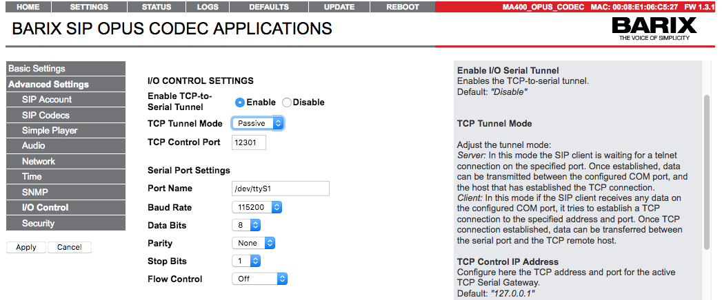
I/O CONTROL SETTINGS
Enable I/O Serial Tunnel
Enables the TCP-to-serial tunnel.
Default: "Disable"
TCP Tunnel Mode
Adjust the tunnel mode:
Server: In this mode the SIP client is waiting for a telnet connection on the specified port. Once established, data can be transmitted between the configured COM port, and the host that has established the TCP connection.
Client: In this mode if the SIP client receives any data on the configured COM port, it tries to establish a TCP connection to the specified address and port. Once TCP connection established, data can be transferred between the serial port and the TCP remote host.
TCP Control IP Address
Configure here the TCP address and port for the active TCP Serial Gateway.
Default: "127.0.0.1"
TCP Control Port
Sets the TCP control port on which the TCP Server shall listen to, or the TCP Client shall try to connect to.
Default: "12301"
Port Name
Configure here the device name of the serial port in use.
Default: "/dev/ttyS1"
Baud Rate
Select the serial transmission speed ("9600" to "115200" Baud).
Default: "9600"
Data Bits
Select "7" or "8" data bits.
Default: "8"
Parity
Select "None", "Even" or "Odd" parity.
Default: "no"
Stop Bits
Select "1" or "2" stop bits.
Default: "1"
Flow Control
Select the type of flow control:
RTS/CTS signals not used: "Off"
RS232: "Software flow control(XON/XOFF)" or "Hardware flow control (RTS/CTS)"
NOTE: On MA400 devices (SIP OPUS Codec) this setting is ignored, since the RTS signal is used as "door relay".
Default: "off"
SECURITY SETTINGS
Reboot Function
Enable or disable the "Reboot" function with the RESET button and from the WEB UI REBOOT tab.
Default: "enabled"
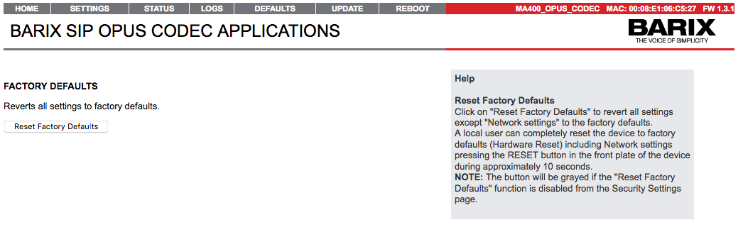
Reset Factory Defaults
Enable or disable the "Reset Factory Defaults" feature from both web UI "DEFAULTS" tab and device front panel RESET button. In order to revert all settings to factory defaults click on the "Defaults" web UI page, or keep the Reset button pressed for more than 10 seconds.
Default: "enabled"
Update Function
Enable or disable the WEB Update function of the device.
Default: "enabled"
Web UI Password
This group of fields is visible as long as no password is set.
Enter the admin password (up to 16 characters) both in the "Password" and "Confirm Password" fields, then click the "Submit" button. After the restart you should close the browser window and open a new browser window. You will be asked to supply user name and password. Use the default admin user name and the password that you have just set in order to access the web UI.
Change Password
This group of fields is visible as long as a password is set.
To allow free access (clearing the password) enter the old password and leave the fields "New Password" and "Confirm Password" empty. After the restart you will not be asked for user name and password anymore.
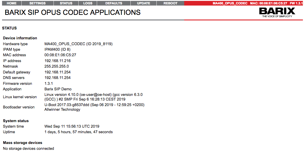
4.3 Status Page
This page prints all available configuration options, and can be used for diagnostic purpose.
4.5 Factory Defaults Page
This page helps you to revert to factory default if needed. To do so please click on "Revert to defaults" link to restore all factory settings except "Network configuration".
While restarting the device a screen appears showing a number counting down. On device start up a screen appears stating the successful reverting to factory defaults.
If you need to revert also the "Network configuration" settings to factory defaults please press and hold the Reset button for about 10 seconds while the device is powered.
4.6 Update Page
This page helps you to do a full, or partial FW update of your device. For more details how to do it please refer to WEB UI ABCL SIP Firmware update chapter.
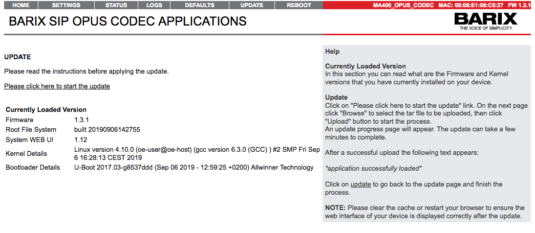
Updating the FW image
Click on "Please click here to start the update" link. On the next page click "Browse" to select the tar file to be uploaded, then click "Upload" button to start the process.
An update progress page will appear. The update can take a few minutes to complete.
After a successful upload the following text appears:
"application successfully loaded"
Click on update to go back to the update page and finish the process.
NOTE: Please clear the cache or restart your browser to ensure the web interface of your device is displayed correctly after the update.
Advanced WEB UI configuration
5 Extra features in the SIP OPUS CODEC application
5.1 Remote CGI Commands
The SIP OPUS CODEC application can be remotely controlled by sending CGI commands. The command must be sent to sip.cgi. If the command is sent with the browser, you should add a random parameter at the end of the POST/GET request to prevent the browser from caching the web page ans show always the same content.
Here is the list of supported commands:
Command | Description | Examples |
|---|---|---|
answer | Forces the SIP Client to accept incoming call | |
get_status | Returns the application status in JSON format which you can process in your control script: { "URI":"sip:1000@192.168.1.100", "call_state":"inactive", "dial_id":"1001@192.168.1.100", "expires":"122", "hasRegistered":"Yes", "mode":"DECODER", "peer_id":"", "rts_io":"OFF", } | |
hangup | Forces the SIP Client to close the active call | |
dial | Dial a specific SIP URI | http://192.168.1.210/cgi-bin/sip.cgi?dial=sip:1001@192.168.1.100 |
send_dtmf_info | Sends DTMF via SIP INFO message | http://192.168.1.210/cgi-bin/sip.cgi?send_dtmf_info=1234*#234 |
send_dtmf_2833 | Sends DTMF in-band | http://192.168.1.210/cgi-bin/sip.cgi?send_dtmf_2833=1234*#234 |
Remarks:
1. You can send the request via the browser, but also using curl/wget commands, for example:
wget
wget -qO- http://192.168.11.216/cgi-bin/sip.cgi?get_status=1
{"URI":"sip:1000@192.168.11.107","call_state":"inactive","dial_id":"1001@192.168.11.107","expires":"168","hasRegistered":"Yes","mode":"DECODER","peer_id":"","rts_io":"OFF"}
curl
curl "http://192.168.11.216/cgi-bin/sip.cgi?get_status=1"
{"URI":"sip:1000@192.168.11.107","call_state":"inactive","dial_id":"1001@192.168.11.107","expires":"535","hasRegistered":"Yes","mode":"DECODER","peer_id":"","rts_io":"OFF"}
2. If your web page is protected by a password, you have to add the user name and the password to the request, for example:
wget
wget -qO- --user=admin --password=adminpasswd http://192.168.11.216/cgi-bin/sip.cgi?get_status=1
{"URI":"sip:1000@192.168.11.107","call_state":"inactive","dial_id":"1001@192.168.11.107","expires":"168","hasRegistered":"Yes","mode":"DECODER","peer_id":"","rts_io":"OFF"}
curl
curl --anyauth -u admin:adminpasswd "http://192.168.11.216/cgi-bin/sip.cgi?get_status=1"
{"URI":"sip:1000@192.168.11.107","call_state":"inactive","dial_id":"1001@192.168.11.107","expires":"535","hasRegistered":"Yes","mode":"DECODER","peer_id":"","rts_io":"OFF"}
Replace “adminpasswd” with the one printed on the sticker on the bottom of your device
5.2 Using the TCP-to serial Tunnel
Transparent Serial-to-TCP passive gateway
This feature allows to transparently transfer data in full-duplex mode between the Serial COM port of the SIP client, and a TCP connected remote host without the need to use the X command.
To enable it, set the “TCP Tunnel Mode” from the “Passive”, and “Enable TCP-to-Serial Tunnel” option to “Enable”. The remote host must open a TCP connection to the SIP client in order the gateway to be functional. The TCP port to which the SIP client will listen for incoming TCP connections is configured via the TCP Control Port option.
To establish the tunnel, you need to setup two things:
First open the serial terminal emulator, and configure it connect to the SIP OPUS Codec Serial port by clicking on Connection→Options from the CoolTerm menubar:
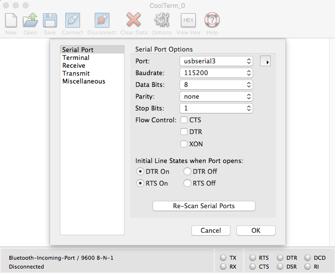
Set the Baudrate, Start/Stop and Flow control bits as configured on the SIP OPUS Codec device. Your serial port name may vary, in this case we are using USB-to-RS232 adapter, that appears as usbserial3 device on the Mac. After configuring all options, click “OK”, then click the “Connect” button to open the COM port device.
Next, open bash prompt on your computer, and run telnet:
my-imac24-2:~ myuser$ telnet 192.168.11.216 12301
Trying 192.168.11.216...
Will map carriage return on output.
Will send carriage returns as telnet <CR><LF>.
Connected to 192.168.11.216.
Escape character is '^]'.
test
============================ start of test file ========================
89:;<=>?@ABCDEFGHIJKLMNOPQRSTUVWXYZ[\]^_`abcdefghijklmnopqrstuvwxyz{|}~
9:;<=>?@ABCDEFGHIJKLMNOPQRSTUVWXYZ[\]^_`abcdefghijklmnopqrstuvwxyz{|}~ !
:;<=>?@ABCDEFGHIJKLMNOPQRSTUVWXYZ[\]^_`abcdefghijklmnopqrstuvwxyz{|}~ !"
;<=>?@ABCDEFGHIJKLMNOPQRSTUVWXYZ[\]^_`abcdefghijklmnopqrstuvwxyz{|}~ !"#
<=>?@ABCDEFGHIJKLMNOPQRSTUVWXYZ[\]^_`abcdefghijklmnopqrstuvwxyz{|}~ !"#$
…...
6789:;<=>?@ABCDEFGHIJKLMNOPQRSTUVWXYZ[\]^_`abcdefghijklmnopqrstuvwxyz{|}
789:;<=>?@ABCDEFGHIJKLMNOPQRSTUVWXYZ[\]^_`abcdefghijklmnopqrstuvwxyz{|}~
89:;<=>?@ABCDEFGHIJKLMNOPQRSTUVWXYZ[\]^_`abcdefghijklmnopqrstuvwxyz{|}~
============================ end of test file ==========================
^]
telnet> quit
Connection closed.
my-imac24-2:~ myuser$
Type the “test” - it should appear in the CoolTerm terminal window. Next, click on Connection-->Send Text File, and select a plain ASCII file to send. The data should start appearing in the telnet window.
When finished, press Ctrl+] and type “quit” to close the telnet session. With this, the established Serial-to-TCP tunnel is destroyed.
Sending metadata using a peer-to-peer TCP-to-serial Tunnel
It is possible to create a transparent TCP tunnel between two SIP OPUS Codec devices, and send data via the serial port of the sending device, and decode these data on the serial port of the receiving device.
A typical use case is in the broadcast industry, where one of the devices is set as encoder, and the other as decoder. In this case you can use the TCP-to-serial feature to send metadata or I/O controls from your your broadcast studio to the broadcasting equipment on the receiving side (typically your antenna broadcast site).
To achieve this, first you need to configure the receiving device in Passive TCP Mode as already described above.
Next, set the sending device in “Active TCP Mode”, and set the receiving device IP as “TCP Control IP Address”

Click “Apply” and the SIP OPUS Codec will start attempting to connect to the remote (passive) device every 10 seconds. Once a TCP connection is established it will immediately start sending all data received on the serial port. Your equipment will get the data from the serial port of the receiving device.
6 Common Issues and Useful Tips
6.1 Using the SIP Opus Codec in P2P mode
“Registration”
If you do not have a SIP account, you can still use the SIP client Peer-to-Peer mode. In this mode the device needs to “register” to itself. For this purpose configure its own IP address as SIP Server/PBX, and leave the password field empty.
Dialing in P2P Mode
Enter the remote peer IP address in the sip: box on the webUI (ex: 192.168.1.101) and then click the “Dial button”.
NOTE1: Some SIP phones may have several SIP lines configured, so they may reject the incoming P2P call with “404 Not found” message because they fail to match from which SIP line this call is coming. To solve this please refer to the user manial of this SIP Phone model.
NOTE2: Most SIP phones accept SIP connections on port 5060. If they use another port, then you need to add it to the dial sting, like: “192.168.1.101:5062”
Receiving a P2P call
In order to receive P2P call, the device does not need to be explicitly configured to “register” to itself. It can receive a P2P call even when is registered to a SIP server. In this case is enough to enter the SIP Opus Codec device IP address on the rempte peer. How you do that may vary on the SIP HW/SW you are using, for example on Siemens Gigaset and Snom SIP phones you can enter the IP address using the “*” as separator, (eg. “192*168*11*216”) and then pressing the dial button.
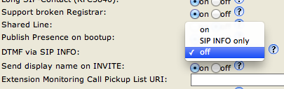
6.2 Door “relay” not activated on DTMF command
Check if the remote SIP telephone has both SIP INFO and DTMF enabled at the same time. If yes-configure it to use only one of these methods. Here is an example how to do it on SNOM 360.
Open the web configuration page, and go to your Identity-->SIP page. Find the option „DTMF via SIP info“, and set it to „Off“:
6.3 Establishing TCP-to-serial Tunnel behind firewall
The scenarios for configuring the TCP-to-serial tunnel, described above, will perfectly work if the two devices are on your private network (LAN). However, this configuration may not work if any of the two devices is not on the same network, or is locate in a network behind a firewal, or NAT. In this case you have 2 options to make it work:
OPTION 1: Use public IP address.
The two devices (or at least the one with the passive TCP connection) must have public IP address. This means tha the device must be exposed directly exposed to Internet without any protection, which might not be safe. To get a public IP address you should contact your Internet Service Provider, and ask for details how to do that. Yo may get either a static, or DHCP network configuration details. Once you receive them, open the SIP Opus Codec wen interface, and configure the network from SETTINGS→Advanced Settings→Network.
OPTION 2: Make a pinhole in your NAT router or Firewall
The most common case is that you will have a router, or a firewall device, connected to the Internet, and your local network just behind it. In most common cases this will be also the DHCP server distributing the IP addresses for your local network.
In this case the SIP OPUS Codec device is not reachable from internet, because your router tries to block all incoming connections to your network devices if it hasn’t been explicitly requested. To allow specific connections to be forwarded to a specific device on the LAN, you will have to add a port forwarding rule on your router. How to do that is out of the scope of this manual, because it may vary depending on the router being used.
However, here you are some configuration basics. Let’s assume that you have configured your router to forward incoming TCP connections to port 12301 to the device with IP address 192.168.1.101 and port 10000 on the LAN as shown on the picture below:
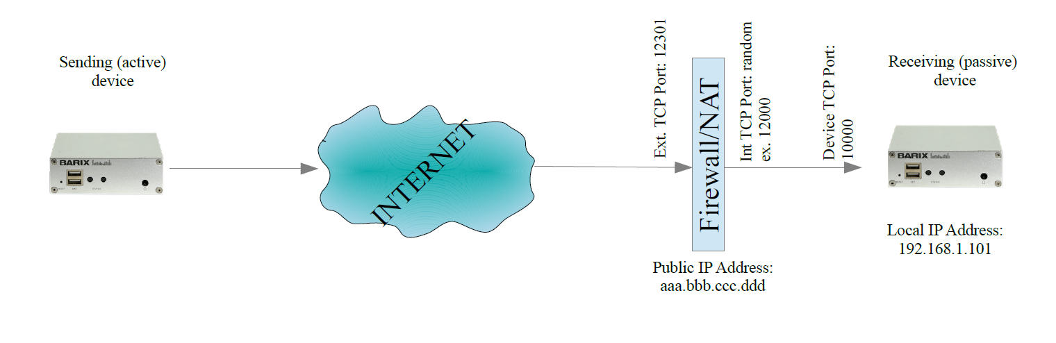
As soon as the router receives incoming TCP connection on port 12301, it opens a random internal port (12000 in the example), and creates a TCP connection to device IP 192.168.1.101:10000. In this way the data are “tunnelled” through the firewall, and the sending device can reach the receiving device.
Now lets configure the devices:
On the sending device
Set the TCP Tunnel Mode to “active”, TCP Control IP Address to your router public IP, and as TCP Control port to “12301”
On the receiving device
Set the “TCP Tunnel Mode” to “passive”, and “TCP Control Port” to “10000”
Now your two devices shall be able to communicate.
Illustration Index
Illustration 1: SIP Client use cases............................................................................................................ 9
Illustration 2: Connecting Annuncicom 100.............................................................................................. 12
Illustration 3: Home page of unconfigured SIP client................................................................................ 13
Illustration 4: SIP client Basic Settings menu page................................................................................... 13
Illustration 5: Home page of a configured and registered SIP client........................................................... 14
Illustration 6: SIP Client Configuration page............................................................................................. 17
Illustration 7: FactoryDefaults page......................................................................................................... 25
7 Compliance and further Information
This equipment has been tested and found to comply with the limits for a Class B digital device, pursuant to part 15 of the FCC Rules. These limits are designed to provide reasonable protection against harmful interference in a residential installation. This equipment generates, uses and can radiate radio frequency energy and, if not installed and used in accordance with the instructions, may cause harmful interference to radio communications. However, there is no guarantee that interference will not occur in a particular installation. If this equipment does cause harmful interference to radio or television reception, which can be determined by turning the equipment off and on, the user is encouraged to try to correct the interference by one or more of the following measures:
Reorient or relocate the receiving antenna.
Increase the separation between the equipment and receiver.
Connect the device into an outlet on a circuit different from that to which the receiver is connected.
Consult the dealer or an experienced radio/TV technician for help.
Safety and precaution recommendations apply. Find them in the download section at www.barix.com
 Find your distributor on this list for more hardware.
For questions that are extending the documentation, feel free to contact us on:
International: +41 434 33 22 22
USA: +1 866 815 0866
Email: support@barix.com
[1] Make sure that ID 1001 is existing and registered to the same SIP server. This could be another BARIX SIP client, or any HW or SW SIP phone.