User Manual
MP3/AAC+ encoder with integrated Icecast Server
This manual describes | Instreamer ICE |
|---|---|
Firmware Version | v1.5 |
Released | 29. November 2021 |
1 Introduction
1.1 What is the Instreamer ICE?
The Instreamer ICE from Barix has two uses: on the one hand, it is an audio network encoder which first converts audio into a data format, then streams the data to remote receivers over the network; on the other hand, it serves as an Icecast server that provides access to streams for multiple listeners/clients.
The Instreamer ICE is equipped with a standard audio interface (RCA /cinch) and a variety of network standard protocols, including the HTTP audio streaming protocol supported by most media players.
It supports MP3 and AAC+ encoding formats, selectable in the setup, and features a built-in server of the popular Icecast audio distribution.
Software Features:
SonicIP© for an easy access to the web interface
Static IP or DHCP (default) capable
Detectable by the „Barix Discovery tool“
DNS support
web interface (HTTP/HTTPS) for configuration
Manual and automatic firmware update
Password manager for UI and Icecast
Audio encoding in MP3 and AAC+ with selectable sample rates & bitrates
Internal Icecast server for up to 100 listeners/clients
Icecast “source mode” to feed external Icecast servers
Stream relay mode (forwarding of external Internet Radio stream)
Import/export of custom stream configurations
Restore factory settings, restore default streaming configuration
Live information about audio and streaming status on homepage
Metadata insertion over RS232, Icecast Admin and via TCP
HTTP Internet Streaming Protocol
Stream authentication for multiple users/listeners
1.2 Applications
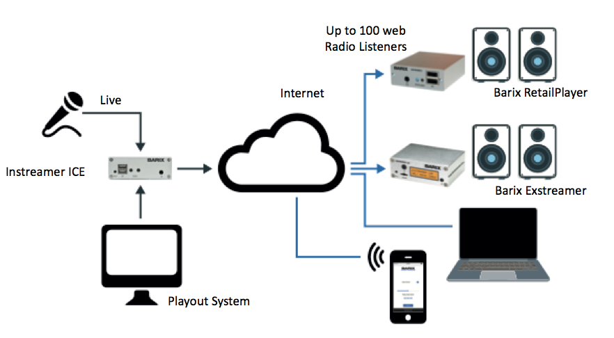
The Instreamer ICE was designed with two applications in mind, namely: it can be used as a live encoder feeding either the built-in Icecast server or an external Icecast server.
1.2.1 Live encoder feeding integrated Icecast server - “Icecast Server mode”
In the “Icecast Server mode”, the Instreamer ICE encodes the analog audio and up to 100 clients/listeners can pickup the audio stream directly from the Instreamer ICE.
1.2.2 Live
encoder feeding external Icecast server - “Icecast Source mode”
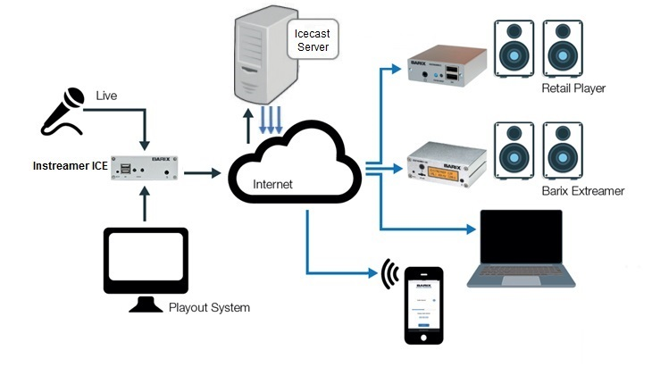
In “Icecast Source mode”, the Instreamer ICE acts as source for an external Icecast server.
It encodes the audio from the audio input and sends the output of the encoding process as a stream to a remote Icecast server. All clients/listeners can then pickup the audio stream from this external Icecast server. This mode is useful when you want to have more internet bandwidth and prefer to use an external Icecast server – i.e. hosted at special Internet Service providers – to provide the stream to your customers.
1.3 About This Manual
This manual is intended for Instreamer ICE users. It describes the device, the possible configurations and the supported communication protocols, among others.
For the installation of the Instreamer ICE, please refer to the corresponding “Quick Install Guide”. A printed version is included in the box and the latest version can be downloaded from our web site at www.barix.com.
1.3.1 Notes, Warnings, and Cautions
Throughout this manual, you will find paragraphs that have a special boxed heading of either "Note", "Warning" or "Caution". These paragraphs contain particularly important information defined by the heading.
Note
Note paragraphs describe information that is important for the reader to understand to avoid functional or procedural problems, but the information does not pose a significant risk of damage to the product or personal injury.
Caution
Caution paragraphs describe information that is important for the reader to understand to avoid potential damage to equipment.
Warning
Warning paragraphs describe information that is critical for the reader to understand and abide by to avoid the risk of personal injury.
1.4 Getting support
1.4.1 Additional documents
The following additional documents are available from Barix for the Instreamer ICE:
- Quick Install Guide
- Release notes
Barix is committed to helping you have a successful experience with the Instreamer ICE. The first help resource should always be to read the manuals carefully. If you still need support after reading the manuals, the following support resources should help answer your question:
1.4.2 Distributors
Check with your Barix distributor for technical support resources they offer. A list of distributors is available on the Barix website.
1.4.3 Barix Help Center
The Barix help center (https://help.barix.com/instreamerice) is a very good support resource and offers the product documentations as also many answers for often asked questions and hints and tricks that may not be included in the manuals.
1.4.4 Email Support
You can email a Barix support technician at support@barix.com.
2 Accessing and configuring of the Instreamer ICE
The Instreamer ICE contains a built-in web server and comes with a web user interface (web UI) that allows you both, to configure various settings of the Instreamer ICE and monitor the status of streaming.
This chapter provides detailed instructions to help you connect the Instreamer ICE to a network and accessing the standard status and configuration pages for the first time.
2.1 Accessing the Instreamer ICE for the first time
2.1.1 Connecting to an Ethernet/IP network
The first step in preparing to access the Instreamer ICE´s configuration and status pages is to connect it to an Ethernet network and assign an IP address to it.
The Instreamer ICE is equipped with a standard Ethernet 10/100 Mbit, full / half duplex, auto negotiation interface. Connect the device to an Ethernet network using an RJ-45 Ethernet cable to network switch or network hub. You'll also need a computer connected to network. If you are going to connect the Instreamer ICE directly to a computer without switch or hub, you must use a "crossover" cable, which is a specially-wired cable available at many electronics supply stores.
2.1.2 Supplying Power
Before you can access the Instreamer ICE's web UI, you must connect the Instreamer ICE to an appropriate power source. Use the power supply which was delivered with your Instreamer ICE. Connect it first to the wall socket and thereafter to the device.
2.1.3 Using headphones to listen IP address
When booted, the device announces the IP address it received from the DHCP Server over the headphone connector. Accordingly, please connect a headphone to the headphone connector on the front of the device to listen to the announced IP address. If you have no headphones or speaker in your reach, you can instead use the Barix Discovery tool to find the device’s IP address instead – see section 2.1.4
Note
Please make sure the Instreamer ICE is properly connected to the network so that it can receive a valid IP address from the DHCP server.
Note
The IP announcement after startup is called SonicIP© and can be disabled later in the setup if not desired or needed.
If you've been successful at finding the IP address of the Instreamer over headphone, you can skip the next section 1.1.4 and continue to chapter 1.1.5.
2.1.4 Using the Barix Discovery Tool
The Instreamer ICE must have a valid IP address before you can use most of the functions available via the Ethernet interface. A simple way to find and/or change the Instreamer ICE's IP address is to use the Barix Discovery Tool.
You can also download Barix Discovery tool from the Barix web site at: https://www.barix.com/downloads (under Software Downloads - Tools).
The Discovery tool is written in the Java programming language, meaning it requires a Java Runtime Environment (JRE) installed on your computer. If you do not have a JRE installed, you can download and install it from: https://java.com/en/download/manual.jsp. Java run time environments are available for all major operating systems. If you are running the discovery tool on a Linux or UNIX platform, the Discovery tool also requires the X-window graphical user interface.
The Discovery tool is distributed in a Java Archive (.jar) file. On most operating systems, you can run the discovery tool by simply double-clicking on the discover.jar file. The tool should start up and the initial screen shown in Figure 1 should appear.
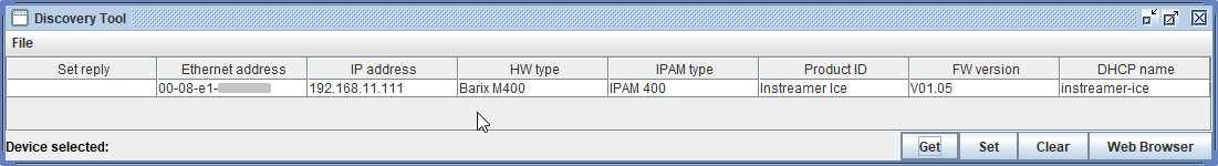
Figure 1. The Barix Discovery Tool helps to find Instreamer ICE on the same local network as the computer running the tool.
Click the "Get" button to initiate a search. If the Discovery tool finds one or more Barix devices on the network, each device will have an entry in the table with the following information listed: current IP address, MAC address (labeled "Ethernet Address" in the Discovery tool), firmware version, among others.
The Discovery tool will find and list all Barix devices that are on the same network as the computer running the tool, regardless of their current IP address setting. The tool will not search through a router to another subnet.
Note
The Discovery tool will be not able to find devices that are using firmwares older than 2011.
The IP address displayed in the Discovery tool is either a dynamic IP address, assigned by a DHCP server, or a fix/configured IP address. The Instreamer ICE has the IP address set to 0.0.0.0 and DHCP enabled, when first used, which means that it will automatically attempt to acquire an IP address from the local DHCP.
If there is no DHCP Server in the network available, the Instreamer ICE will fail to obtain an IP address. Nevertheless, the Barix Discovery tool will find it and show the IP address 0.0.0.0 (which is inaccessible).
You can set the address in the Discovery Tool by double clicking on the IP address field of the Instreamer ICE you wish to change. Doing so will make the IP address field editable. Enter the IP address you want to assign to the Instreamer ICE, then click "Set" at the bottom of the Discovery tool. The "Set reply" field displays "No error" if the address assignment was successful.
Before you can access the Instreamer ICE, make sure it was given a proper IP address. You can use the address that appears in the Discovery tool to access the Instreamer ICE via a web browser. However, keep in mind that the IP address assigned via DHCP may change if the Instreamer is rebooted.
If you decide to assign a static IP address to the Instreamer ICE, you must make sure to use an address that is outside the range of addresses that are automatically assigned by any DHCP server on the network.
2.1.5 Accessing the device setup with a Browser
You can now access the Instreamer ICE web pages by using your web browser. We recommend Chrome and Firefox.
Open your browser and in the address bar type:
http://<IP address>/
Substitute the IP address of your Instreamer ICE for <IP address>. For example, if the IP address 192.168.10.108 was assigned to your device, enter the following in your browser's address bar:
Your browser should display the login page of the Instreamer ICE's. There are two options for the “User” field: you can either to login as “admin” to be able to make any configuration changes or as a “user” to simply view the device’s state. You will find your device’s unique “admin” password written on the backside of the Instreamer ICE. Use it to fill the password field and click on LOGIN button. For devices produced after March 12th 2019, the “user” password is set to “user” by default – we advise you to change it on first use. For devices produced before that, the “user” password is the same as the “admin password”
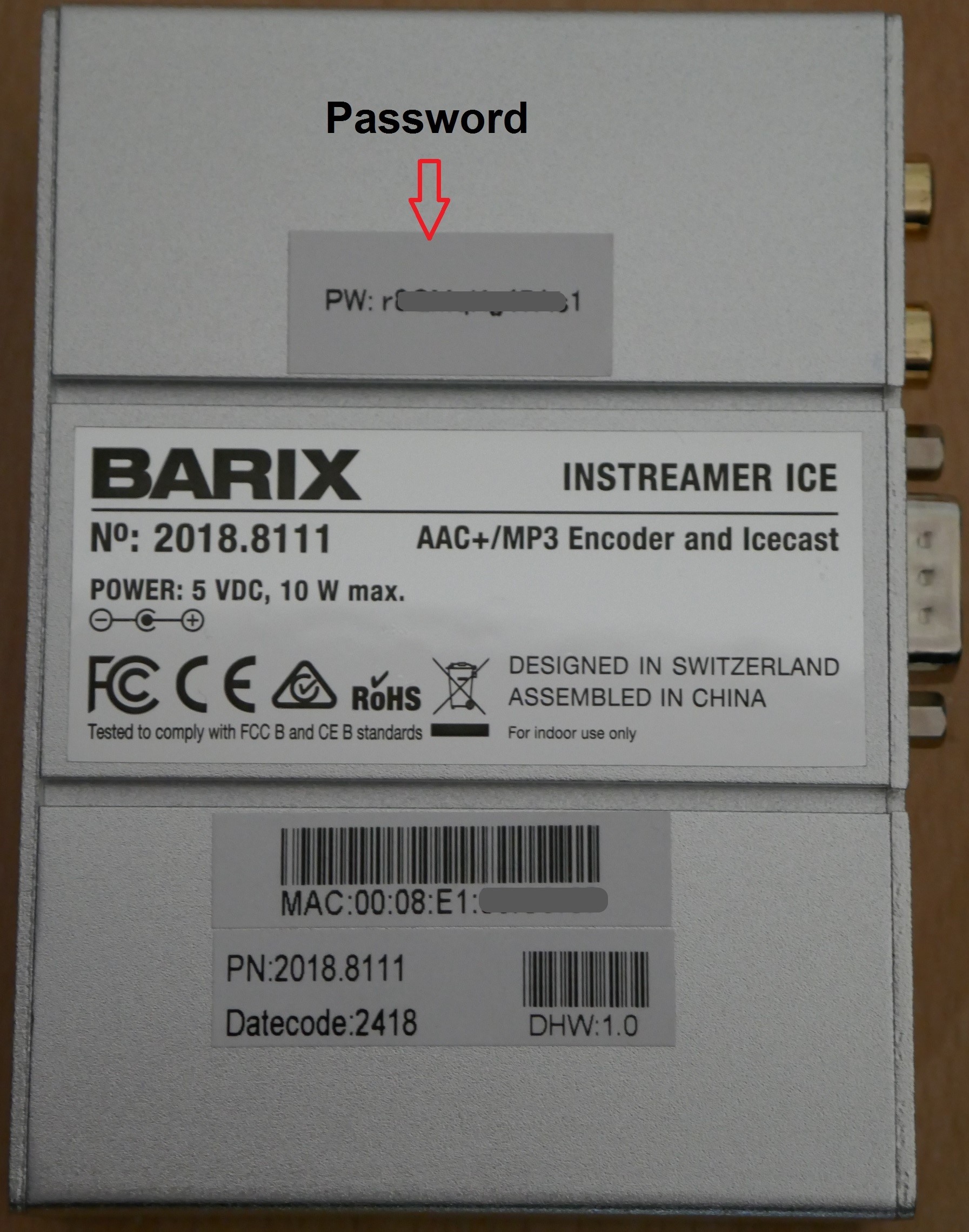
Note
Each Instreamer ICE has an unique default “admin” password written on the backside of the device.
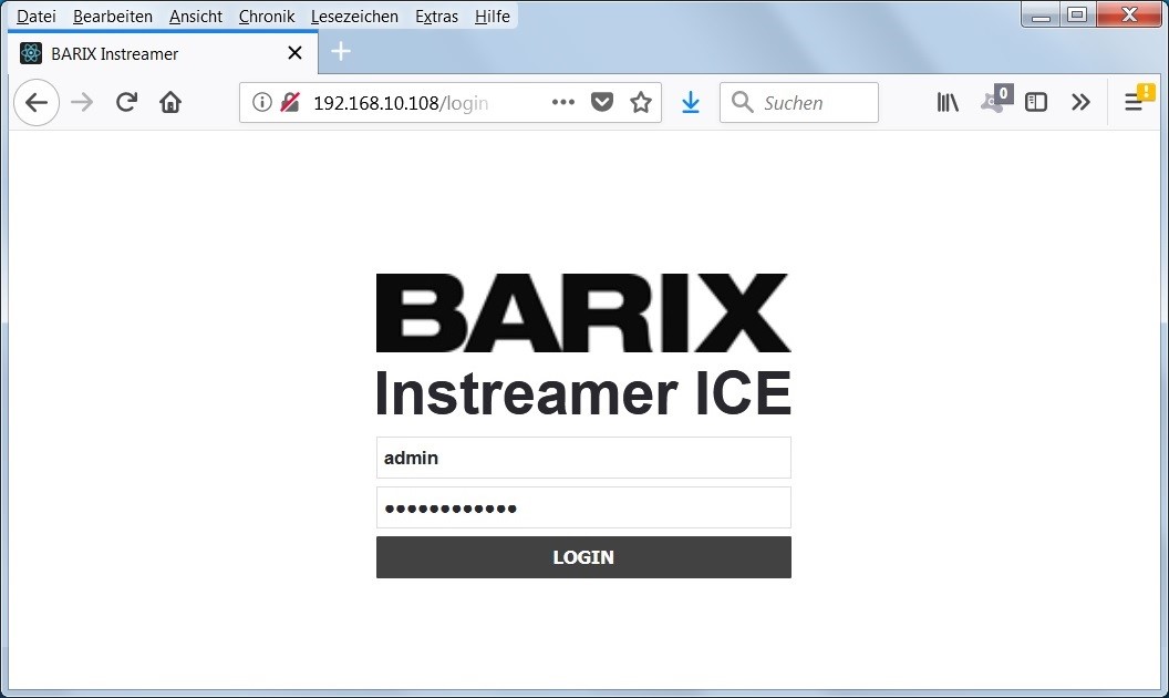
Illustration 1: Login page
A successful login will lead to the Instreamer ICE´s HOME page.
From there, you can access to all other pages and configure the device.
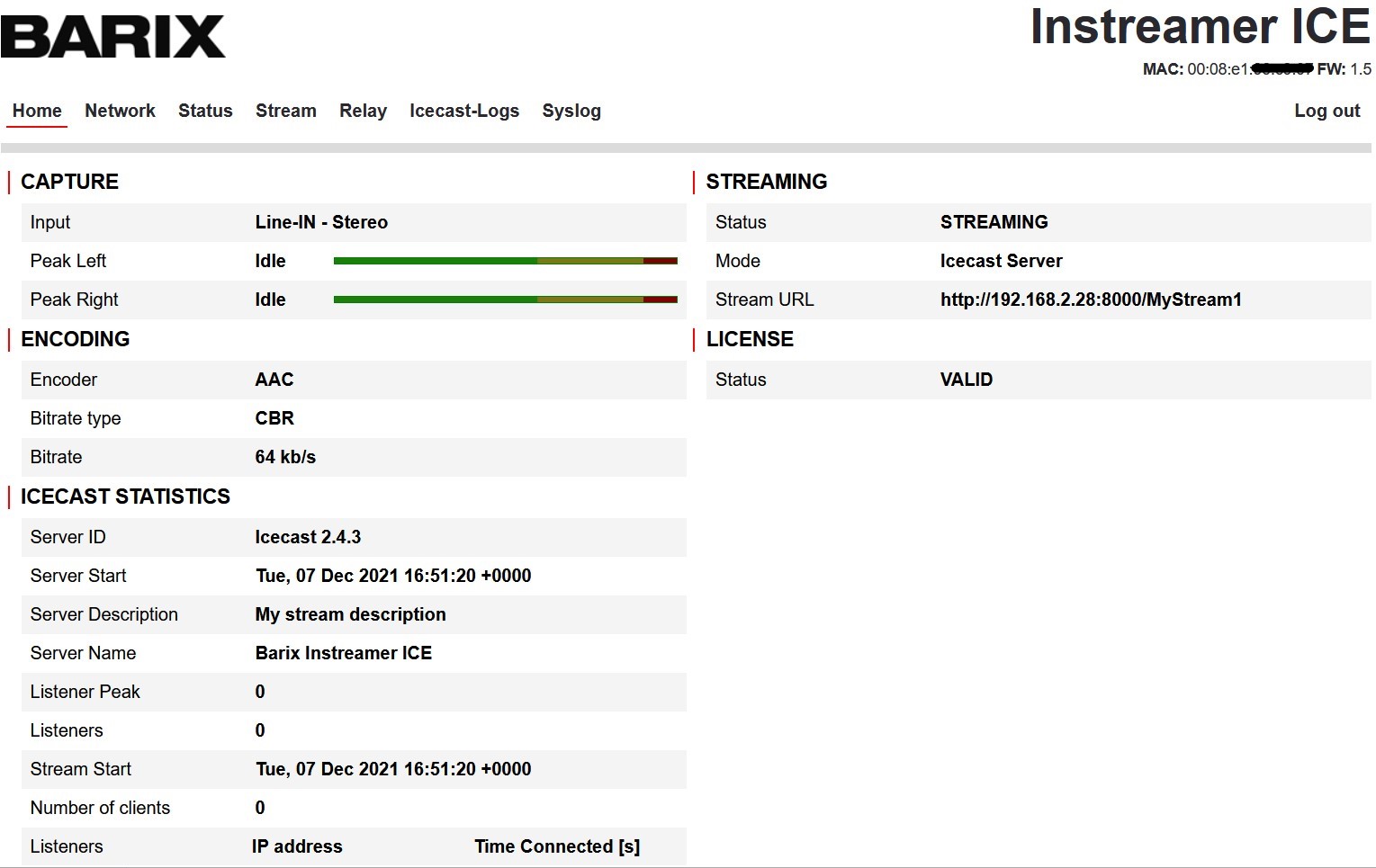
Illustrastion 2: Homepage
3 Hardware
3.1 LED
The status LEDs are located on the left side of the device’s front, next to the two EXT sockets for USB devices. They operate in three states – off, on, blinking – and three colors – red, orange, green.
The status LEDs have following function:
- LED1 or left LED – reflects system status
- LED2 or right LED – reflects application status
Status LEDs description | LED1 System Static | LED1 System Blinking | LED2 Application static | LED2 |
|---|---|---|---|---|
System not powered | OFF | OFF | OFF | OFF |
System booting | RED | OFF/RED | ||
Factory default reboot | GREEN (fast) | GREEN (slow) | ||
System IP Conflict | RED | OFF | ||
System in Rescue mode | ORANGE | OFF | ||
System in Reset Rescue | ORANGE | OFF | ||
System ready | GREEN | |||
Application not running | GREEN | OFF | OFF | |
Application encoding | GREEN | GREEN | ||
Application encoding | GREEN | ORANGE | ||
Application encoding | GREEN | RED | ||
Application encoding | GREEN | GREEN |
3.2 Headphone connector
The headphone out is located on the right side of the device’s front side. It is used to listen to the SonicIP© during the boot only.
3.3 Reset button
The reset button is on the left side of the device’s front and is marked with the text “RESET”. The reset button features four behaviors:
Reset button action | Description | Comments |
|---|---|---|
Short press (<1s) | Device reboots, i.e. - Application stops cleanly - Device restarts | |
Long press (>10s) | Device resets its factory defaults - All factory settings are set - Application stops cleanly - Device restarts with default factory settings | |
Plug out power, Press and hold, plug in power, hold until LED turns orange (about 30s) | Rescue mode - Device downloads and installs latest firmware | Device must be connected to the DHCP network with internet access in order to download and install latest firmware ! |
Plug out power, Press and hold, plug in power, hold until LED turns orange (about 34s) and blinks fast | Rescue mode + network factory defaults - Device downloads and installs latest firmware - Device uses DHCP (network default settings) to deal with IP address attribution | Device must be connected to the DHCP network with internet access in order to download and install latest firmware ! |
3.4 Power
The device comes with his own external power supply, it is rated with 5VDC 2A.
Do not use any other power supplies which provide the device with a different voltage. The power jack on the power supply to the device is male connector: 5,5 * 2,1 mm.
The power connector on the device is located on the backside of the device.
3.5 LAN
The network connector is on the backside of the device. It is a RJ45 10/100 Mbit Ethernet interface, auto-sensing. There are two LEDs on the top of the network connector. As soon the network interface is initialized during boot, the right LED will show any incoming or outgoing network traffic. The left LED is showing the current network link state.
3.6 RS232
The Instreamer ICE provides an RS-232 serial interface. The RS-232 interface is supplied as 9-pin sub D male connector, wired as a DTE. The connector's DTE wiring is similar to a personal computer's serial port, as defined in the following table.
Pin | Direction | Function |
|---|---|---|
1 | No connection | |
2 | To Instreamer ICE | RxD Receive Data |
3 | From Instreamer ICE | TxD Transmit Data |
4 | No connection | |
5 | From Instreamer ICE | Ground |
6 | No connection | |
7 | From Instreamer ICE | RTS (Ready To Send) |
8 | To Instreamer ICE | CTS (Clear To Send) |
9 | No connection |
Caution
The baud rate for the RS-232 port is not configurable! This serial RS232 Interface can be used to insert Metadata to the audio stream. It works with fix serial settings:
115200 baud
8 data bit
1 stop bit
No parity
No flow control
3.7 EXT. ports
The two EXT. ports (to connect USB devices) are not used in this release.
3.8 Line IN (RCA/Cinch input)
The Line IN audio input is on the backside of the device. It is stereo interface for analog Cinch cables.
4 User Interface
4.1 Overview
The Instreamer ICE’s web UI features 6 pages: Login, Home, Network, Status, Stream, Relay, Icecast-Logs and Syslog. The role of each page is discussed below.
4.1.1 Login
Displays the login option. You can login as an administrator using the user “admin” or as a normal user “user”. The default password for the “admin” users is printed on the bottom side of the device. The default password for user is “user” and should be changed on first use.
4.1.2 Home
Display status of the device: streaming status, streaming mode, streaming destination, internal Icecast server statistics and a summary of the encoding options selected.
4.1.3 Network
Displays current network configuration of the device and allows to modify the network settings.
4.1.4 Status
Displays a summary of hardware and software characteristics. Provides access to password management, firmware update (automatic and manual), and reset to factory defaults.
4.1.5 Stream
Displays a summary of the current input, encoder, and streaming configurations. The “admin” user is provided with the following buttons:
“Edit” – to configure the stream
“Reset” to re-load the new configuration;
“ON”/”OFF” switch for the stream operation;
“Import”/”Export” existing configurations; a reset button to return to default configuration.
For all users, there is:
a link to the Icecast mountpoint’s URL
a media player to listen to the content of the built-in Icecast server, if available.
4.1.6 Relay
Only visible to “admin”. Displays set-up options for an Icecast Relay.
4.1.7 Icecast-Logs
Only visible to “admin”. Displays both access- and error logs of the internal Icecast Server
4.1.8 Syslog
Only visible to “admin”. Displays logs of the Instreamer ICE.
4.2 Network page
4.2.1 Network Settings
To configure the device’s network settings, click the “Network” item of the top menu.
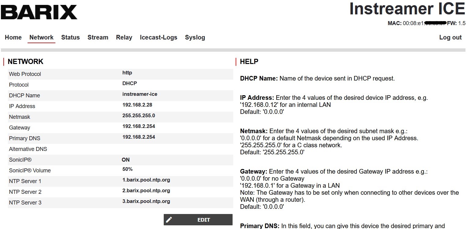
Illustrastion 3: Network page
To enter the configuration mode, click on the “EDIT” button on the bottom left of the “Network” section.
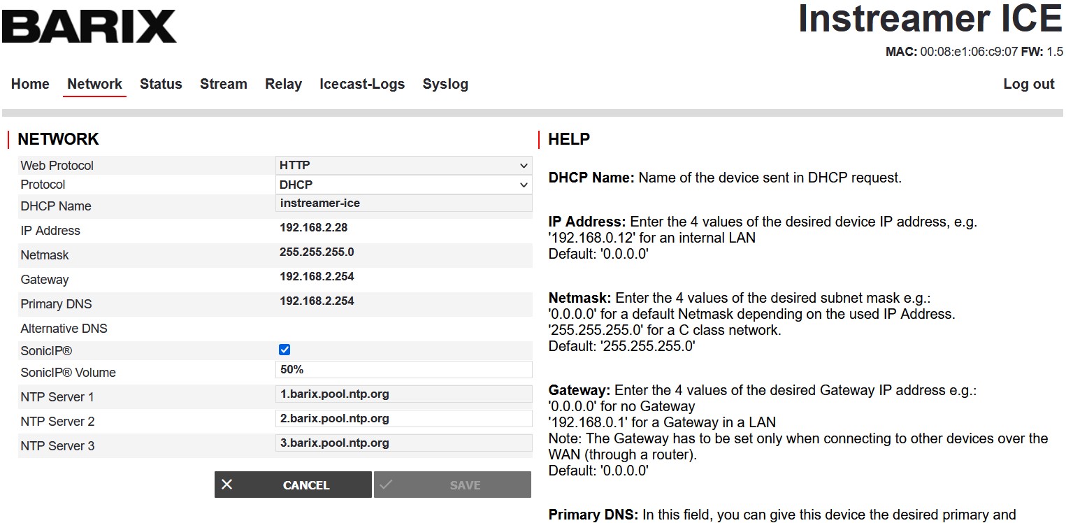
Illustration 4: Network editing
At any time, you can click on the “CANCEL” button and void the current changes you made. To save and activate settings you made, click on “SAVE”.
4.2.2 Web Protocol
Select here the desired web protocol to browse the Web UI. If HTTPS is selected then a private certificate is used (see more details in chapter 7), that will cause a security notification on your browser.
Default setting is “HTTP”.
4.2.3 Protocol
Configure here to set the IP address manually (option: “Static”) or to use the automatic IP address via DHCP (option: “DHCP”). Default setting is “DHCP”.
Choosing DHCP disables the possibility to configure an IP address, netmask or gateway, because these values are assigned by the DHCP server.
4.2.4 DHCP name
If you choose your protocol to be “DHCP”, you can change the DHCP name of the device that is sent in the DHCP request. When DHCP is enabled and no name is defined, it will use “instreamer-ice”. Make sure that the same DHCP name is not used twice in your network; in that sense, it is recommended to change the DHCP name when you first use the device.
4.2.5 IP Address
When “Static” IP address is selected, a manual IP address needs to be configured. Make sure the IP address is unique in your network and fits with the local net address.
If you are unsure about free IP addresses you could use for the Instreamer ICE, please contact your network administrator.
4.2.6 Netmask
The Netmask parameter defines the range of addresses in the current subnet. Addresses outside this range must be "routed" through a device called a "router".
If the Instreamer gets its IP address from a DHCP server, it will also get a netmask from the DHCP server.
In general, it's best to assign a specific netmask, based on the configuration of your network. If you are unsure what netmask is appropriate for your subnet, contact your network administrator. Take a look at Appendix G: IP Addresses, Netmasks and Gateways for more information. Assuming that the Instreamer ICE is connected to the same subnet as your computer, you can probably use the same netmask as your computer.
4.2.7 Gateway
The gateway settings tell the Instreamer ICE the IP address of a router or host that is responsible for forwarding any network traffic that is not within the Instreamer ICE´s subnet. In a small network connected to the internet, the gateway IP address is typically the address of the router that connects the network to the internet (which is probably also the DHCP server). The gateway address is not necessary unless the Instreamer ICE will need to communicate with devices outside its own network. For example, if the Instreamer ICE needs to send a stream to a computer that is outside the Instreamer ICE network, the gateway address is required in order for the Instreamer ICE to connect to the gateway to forward the traffic to its final destination.
The gateway IP address is always in the same subnet as the Instreamer ICE. For example, in a small network where the Instreamer ICE is assigned an IP address of 192.168.0.6, the gateway address might be 192.168.0.1.
If the Instreamer ICE uses DHCP to acquire its IP address automatically, the DHCP server will typically also supply a gateway IP address. In those cases, you can leave the gateway IP empty.
If you are unsure what to set the gateway address to, contact your network administrator. Assuming that the Instreamer ICE is connected to the same subnet as your computer, you can most likely use the gateway address setting of your computer.
See Appendix G: IP addresses, Netmasks and Gateways for more information.
4.2.8 Primary/Alternative DNS
If no DHCP server is used, the IP address of the DNS (Domain Name Service) server should be defined here. A DNS server is needed to resolve DNS name, e.g. www.barix.com and learn the real IP address behind this name.
The Alternative DNS server can be configured for the case the primary DNS server fails.
4.2.9 SonicIP©
SonicIP© stands for the announcement of the current IP address of the Instreamer ICE at boot. If enabled, the device announces its configured IP address over the headphone connector – plug a headphone there to hear it. Default is marked (enabled).
4.2.10 SonicIP© Volume
Here the volume level for the IP address announcement can be configured.
4.2.11 NTP Server 1/2/3
Configure here the NTP server (Network time) and the backup NTP servers.
4.3 Status page
If you need to check the device’s software information, click the “Status” item of the top menu. On this page, you will also be able to manage the following features: firmware updates, passwords and restoring the device’s factory settings.
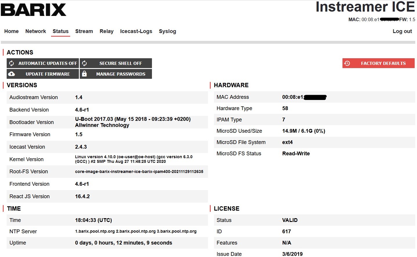
Illustration 5: Status page
4.3.1 “Hardware” section
This section displays information regarding the hardware of your device. These can be useful when our support team need to identify the device, for instance.
4.3.2 “Time” section
This section displays time information such as local time and device up-time.
4.3.3 “Versions” section
This section displays information concerning the software of your device. Our support team uses this to identify the firmware and modules that your device is using.
4.3.4 “License” section
This section displays information about your device’s license. The Instreamer ICE’s functionality is only available if the license status is “VALID”.
4.3.5 Changing the password
You can change the default password on Status Tab, there click “Manage Passwords”. On the upcoming window, you can change the “admin” password, the “user” password and the “Icecast admin“ password.
Select which password you like to change. Next, go to the field “Current Password” and type the current password. After that, type the new password you will assign to device in the fields “New Password” and “Repeat New Password” and click OK to confirm.
In the two first cases (admin and user), the web UI will be reloaded and you will be asked to log in. In any case, the newly set password will be active immediately after confirming the change.
At any time, you may recover the default passwords by returning to factory settings – press the reset button for ca. 10 seconds until LED1 starts blinking fast.
Remember: the “admin” password is printed on the backside of the device; the “user” default password is “user”; the default “Icecast admin” password is “barix_icecast”.
Caution
Protect your device properly, change the default “user” password and the default “Icecast admin” password to secure your Instreamer ICE!
4.3.6 Firmware update
The Status page provides two ways of updating the firmware: on the one hand, you update the firmware manually using the “Update Firmware” button; on the other hand, you can enable/disable the automatic update that fetches a new firmware, if available, on a Barix update server.
For the “Manual update”: first, fetch the firmware file from Barix’s website; second, click on the “Update Firmware” button; third, either use the drag-and-drop feature or click on the top surface to browse and select the firmware file. After that, the firmware will be uploaded and the log will report the progress. Please stay on the page – the process can take up to 2 minutes and is finished when the web interface is reloaded and you are presented with the login page again.
The “Automatic update” takes place on the night between Monday and Tuesday, between 4am-5am, in order to minimize the disturbances. This process only happens if there is a newer firmware available for upload on Barix’s update server. You can disable this feature by clicking on “Automatic Updates ON/OFF”.
Note
If the button reads “AUTOMATIC UPDATES ON”, the automatic update feature is enabled.
If the button reads “AUTOMATIC UPDATES OFF”, the automatic update feature is disabled.
4.3.7 Restore Factory defaults
Use the red “Factory Defaults” button to reset both the network settings and the streaming configuration – but not the passwords. Beware: network settings and streaming configuration will be lost!
4.3.8 SSH
This feature is reserved for our support.
4.4 Streaming actions
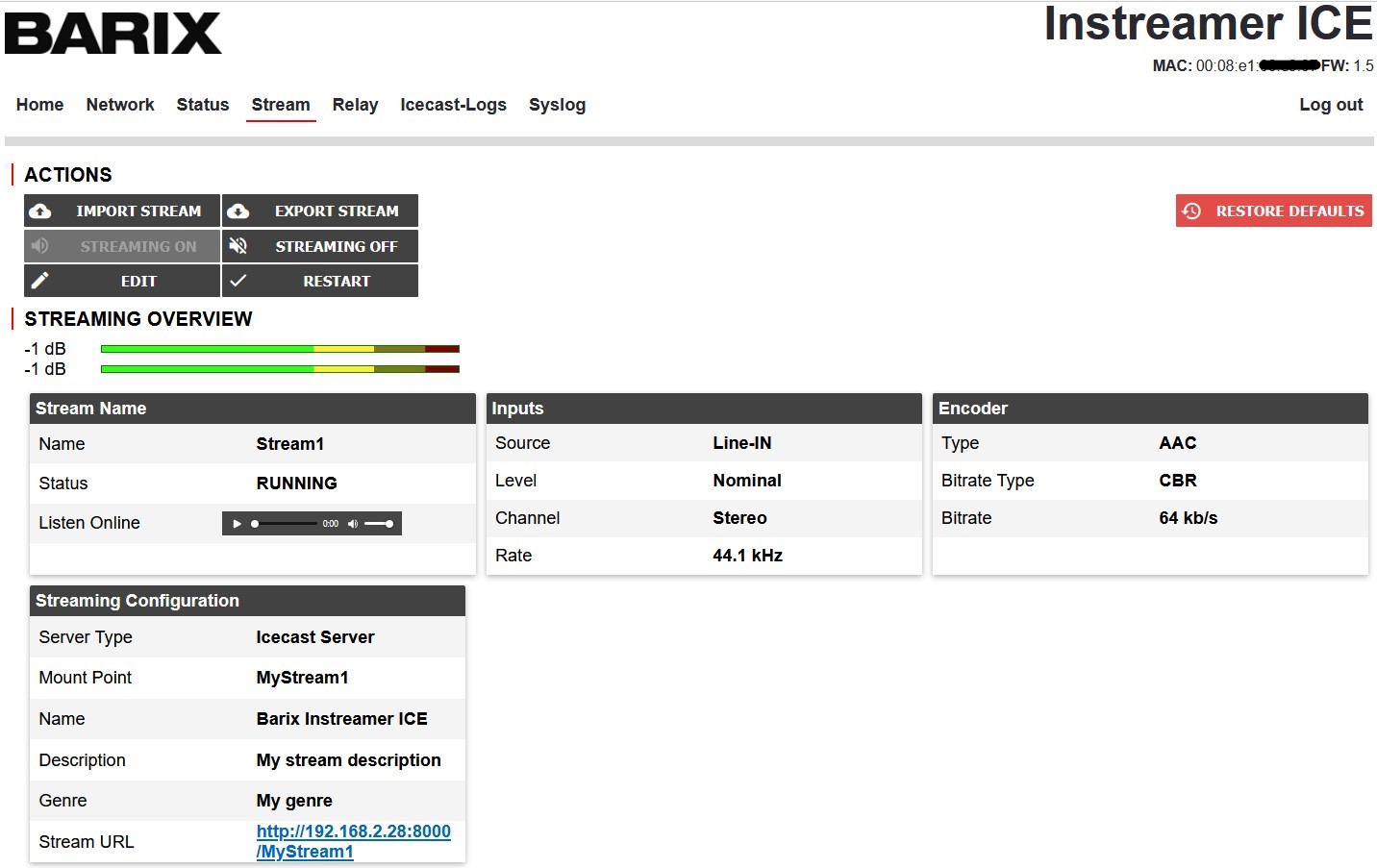
Illustration 6: Stream page
4.4.1 Edit
Click on this button to open the streaming configuration wizard. This will allow you to set up the different parts of the stream: capture, encoding, and streaming.
4.4.2 Restart
Click on this button to restart the application.
4.4.3 Export Stream
Use this button to save the current stream configuration to your PC.
The saved file can be used as backup or to restore the stream configuration later.
4.4.4 Import Stream
Use this button to restore a stream backup file from the PC back to the Instreamer ICE.
4.4.5 Streaming ON
When the device is rebooted the stream starts automatically, but when the stream was manually stopped before, then the Stream can be started again by using the “Streaming ON” button.
4.4.6 Streaming OFF
This button allows you to interrupt the streaming at any time.
4.4.7 Restore Defaults
Press this button if you wish to return to the default streaming parameters and restart the application.
4.5 Stream settings
To configure the streaming settings, click the “Edit” item of the top menu.
Both will open the Stream configuration window where the Stream settings can be configured. After configuration the stream settings, click “OK” to save the settings.
To confirm the change and load the new settings, click on “APPLY CHANGES”.
4.5.1 Stream Name
The stream name is used only for internal identification on the Instreamer ICE. Assign any unique name to it. This name has no influence on the output stream.
4.5.2 Input Source
The audio input for the encoding can be selected in this drop-down menu
On the Instreamer ICE, only one option is available: Line IN.
4.5.3 Input Level
The input/volume level can be used to change the amount of amplification applied to the audio input to increase or decrease volume. Select “Nominal (0 dBu)” for no amplification or “Consumer (-10dBu) for an amplification of the audio input signal.
4.5.4 Input Channel
Select which audio channels of the selected Input Source (Line-IN) should be used for the encoding, “Stereo” (both), “Mono Left” or “Mono Right”.
4.5.5 Sampling Rate
Choose the desired sampling frequency from the drop-down menu. The following options are available: 22.05 kHz, 32 kHz, 44.1 kHz and 48 kHz.
A higher sampling frequency generates to more information, i.e. better quality, depending on the bitrate you choose in the next step.
4.5.6 Encoder Type
Select the audio codec you will use for encoding, that is, either AAC or MP3.
Both are very common audio compression standards with a very good quality.
AAC is more efficient than MP3, especially for lower bitrates and the Variable Bit Rate mode – see next paragraph.
4.5.7 Bit Rate Type
Choose from Constant Bit Rate (CBR) or Variable Bit Rate (VBR).
A stream in variable bitrate usually requires less network bandwidth and could, theoretically, have a better audio quality. The required network bandwidth for the stream depends from the sent audio. For instance, a record of a human voice usually needs less bandwidth than music.
In constant bitrate mode, the stream always uses the same network bandwidth, independently from the audio content (voice, music or no audio at all). The advantage of CBR is better compatibility with players.
4.5.8 Bitrate
Choose here the desired bitrate.
A higher bitrate represents better quality, but generates more network data.
Note
The available bitrates will change depending from selected “Encoder Type” and “Sampling Rate”.
Note
Make sure to have enough network bandwidth available, especially when multiple listeners are connected to the Instreamer ICE over the Internet.
4.5.9 Server Type
Select here the mode you want to use. Select “Icecast Server” if you want your listeners to connect directly to the Instreamer ICE and listen the stream from its built-in Icecast server. Alternatively, select “Icecast Source” if you want the Instreamer ICE to feed a different, external Icecast server. Please see chapter 1.2 - Applications for the two different modes.
4.5.10 Icecast Name
Configure name of the stream. This name will be used in the metadata and shown to the listeners by their media players. Use the Icecast to display your station name, for example.
4.5.11 Icecast Description
The description is an opportunity to display a more precise description to your stream or the content of the stream. This will also be part of the metadata and shown on the listener´s media player.
4.5.12 Icecast Genre
Set here the Genre of your your stream content, e.g. Pop, Jazz or Classic. This will also be part of the metadata
4.5.13 Mount Point
The mount point is part of the path which is used to request the stream from the Instreamer ICE. Configure here your the mountpoint’s name.
Default is “MyStream1”, that means the stream can be requested on the Instreamer ICE from the path “http://ipaddress:port number/MyStream1”
Caution
The mount point of the path is case sensitive!
Note
By using the file extension “.mp3” at the end of the Mount Point, you can make the stream easier accessible for mobile devices or browsers, e.g. MyStream1.mp3 .
4.5.14 Remote URL
This setting is only configurable in “Icecast Source” mode.
Configure here the IP address where the remote Icecast server is available.
That can be the IP address of the Icecast server directly or, when a firewall is used in front of the remote Icecast server, the IP address of the remote firewall.
4.5.15 Audio Port
In Icecast Server mode configure here the port number for the local Icecast server.
In Icecast Source mode configure here the port number of the remote Icecast server.
That can be the port number of the Icecast server directly or, when a firewall is used in front of the remote Icecast server, the opened port number of the remote firewall.
Default is port number 8000.
4.5.16 Username
This setting is only configurable in “Icecast Source” mode.
Configure here the username for the authentication on the remote Icecast server.
4.5.17 Password
This setting is only configurable in “Icecast Source” mode.
Configure here the password for the authentication on the remote Icecast server.
4.6 Relay settings
Relaying is the process by which one server mirrors one or more streams from a remote server. The servers need not be of the same type (i.e. Icecast can relay from Shoutcast). Relaying is used primarily for large broadcasts that need to distribute listening clients across multiple physical machines.
Instreamer ICE implement the so-called (from Icecast documentation) “second type” of Relay.
It’s a specific mountpoint relay: the slave server is configured with a server IP, port and mountpoint and only the mountpoint specified is relayed.
Both mount points, the one from the Relay section and the one from the Stream section, will work in parallel.
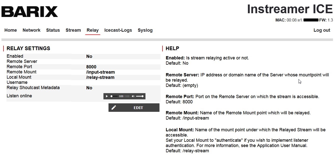
Illustration 7: Relay page
4.6.1 Enabled
Enable or disable here the Relay function.
Default: No (Disabled)
4.6.2 Remote Server
Set here the IP address or domain name of the Server whose mountpoint will be relayed.
Default: (empty)
4.6.3 Remote Port:
Set here the Port on the Remote Server on which the stream to be relayed is accessible.
Default: 8000
4.6.4 Remote Mount
Set here the Name of the Remote Mount point which will be relayed.
Default: /input-stream
4.6.5 Local Mount
Set here the Name of the mount point under which the Relayed Stream will be accessible.
Set your Local Mount to "authenticate" if you wish to implement listener authentication (see section 4.7).
Default: /relay-stream
Caution
The mount point of the path is case sensitive!
Note
By using the file extension “.mp3” at the end of the Mount Point, you can make the stream easier accessible for mobile devices or browsers, e.g. MyStream1.mp3 .
4.6.6 Username
If authentication is active on the Remote Server, set here the username to connect to Remote Mountpoint.
Default: (empty)
4.6.7 Password
If authentication is active on the Remote Server, set here the password to connect to Remote Mountpoint.
Default: (empty)
4.6.8 Relay Shoutcast Metadata
In addition to relaying the stream's content, it’s possible to relay the metadata too. Set here to enable metadata relaying.
Default: No
5 Listener Authentication
Listener authentication is a feature of Icecast which allows you to secure a certain mountpoint such that in order to listen, a listener must pass some verification test (typically inserting user/password).
5.1 Enable authentication
To enable streaming authentication just name in the Stream settings the mountpoint (normal or relay) as “authenticate”.
You can manage it through Mountpoint /authenticate - Manage Authentication page of Icecast Admin web interface. To login use user name “admin” and “Icecast admin” password of the Instreamer ICE.
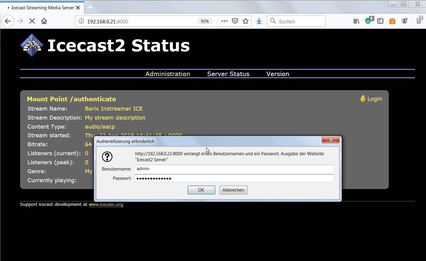
Illustration 8: Icecast UI login
After login scroll down until mountpoint menu to manage the authentication.
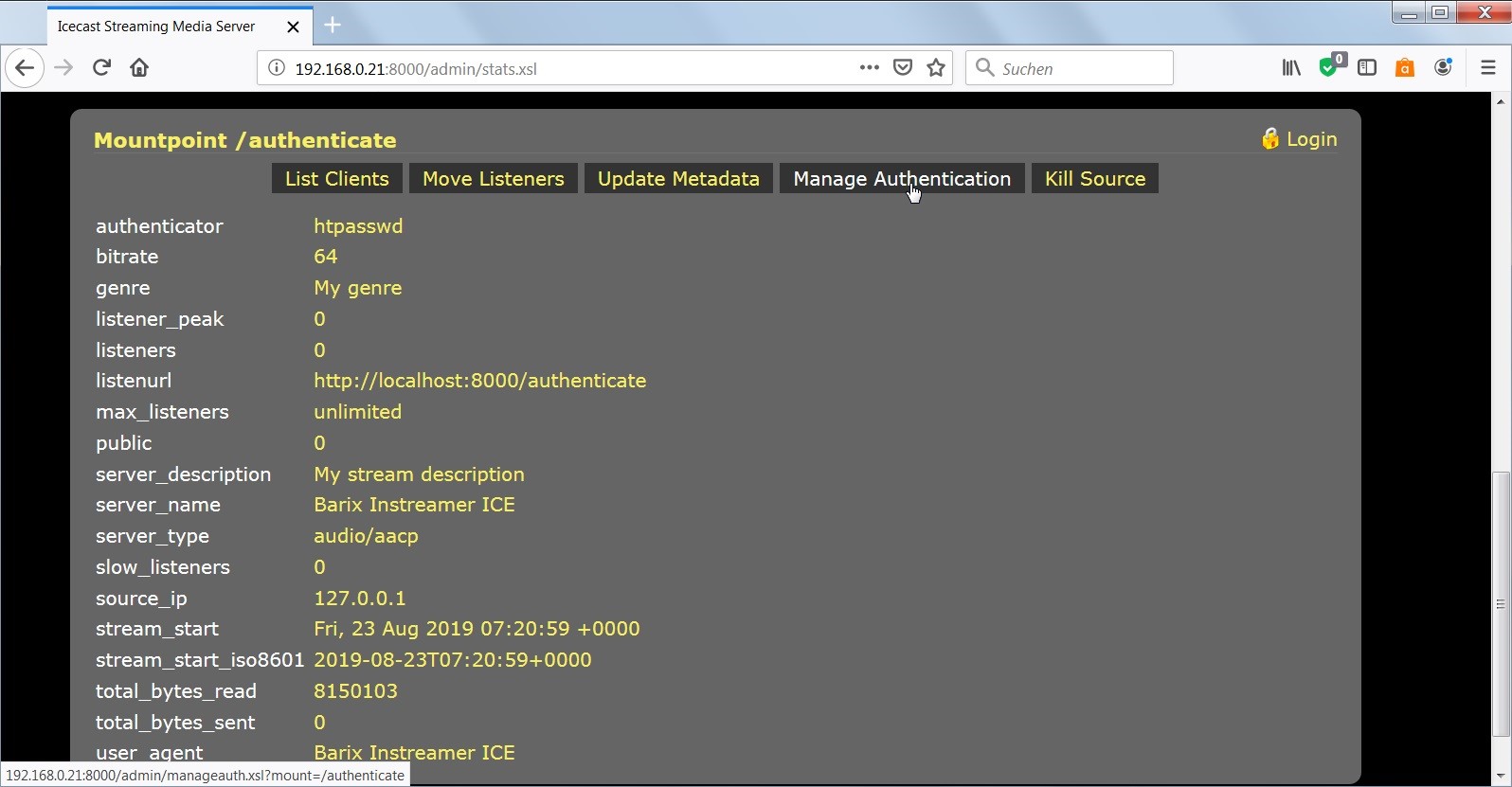
Illustration 9: Manage Mountpoint authentication
6 Inserting Icecast metadata to the audio stream
Metadata are additional information in the audio stream that can be displayed on the receiving audio player. An example of such metadata is song information matching the currently played song. On the Instreamer ICE, this metadata can be added over the serial RS232 interface or over the TCP port 10000. All inserted meta data are even shown in the LOG file
Note
This feature is only available in the “Icecast Server mode” in this version.
To complement your stream with metadata, follow the instructions below:
6.1 Using RS232 port for Metadata
To insert metadata over RS232, connect your PC with a serial null-modem cable or a serial cross cable to the Instreamer ICE. On the PC, open a serial terminal emulator ( e.g. Termite or Hyperterminal) with following settings:115200 baud, 8 data bit, 1 stop bit, no parity, no flow control. Make sure Linefeed (0x0a) is sent as termination character.
Note
Please refrain from using the character ‘ (single quote) in this release.
6.2 Using TCP port for Metadata
The Instreamer ICE offers this function over port TCP port 10000.
Open TCP connection to this port and send your data string terminated by a Linefeed (0x0a).
Note
Please refrain from using the characters ‘ (single quote) and the = (equal) in this release. Instead of the “=” sign use “%3D”, if needed
6.3 Using Icecast Admin interface for Metadata
The Instreamer ICE offers an Icecast Admin interface on TCP port 8000. Open this with your browser, e.g: http://ip-address:8000 .
Login as Icecast admin (admin) thereafter you can insert metadata over the “Update Metadata” button, please see picture 9.
7 Using HTTPS web access
The Instreamer ICE is supporting HTTPS for web configuration access. If enabled thenyou can only login over the HTTPS port to the Instreamer ICE web configuration. On HTTP port 80 is this case no login possible anymore.
When HTTPS is enabled you can reach the setup with :
https://ip-address
e.g.: https://192.168.0.21
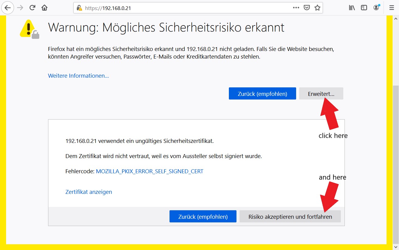
Illustration 10: Warning before HTTPS access
As HTTPS certificate the Instreamer ICE is using an own certificate, not from a public certificate server. For that reason you will get a security alert/warning in your browser. This warning can be ignored. Please click “Advanced” – “accept and continue” to browse the device setup, thereafter you can continue as usual with the login procedure.
In the current version of the Instreamer ICE firmware it is not possible to add own security certificates to prevent this warning.
The HTTPS access is only for the Instreamer ICE setup available, not for the internal Icecast server on port 8000.
8 Maintenance & Service
The Instreamer ICE usually needs no maintenance; it is free of moving parts or moving mechanics. However, it makes sense to install the latest firmware to obtain latest fixes and new features for your Instreamer ICE. To update the firmware you have two options: you can either set the automatic firmware update option to “ON” or use the manual firmware update feature using the Instreamer ICE user interface. You will find the latest firmware on the Barix homepage.
8.1 Automatic Firmware Update
This function is disabled per default. If enabled, the Instreamer ICE will check every Tuesday morning between 4am and 5am of your timezone if a new version is available on the Barix update server. If it is the case, the new version of the firmware will be downloaded and installed on your Instreamer ICE.
To enable the function click the button “AUTOMATIC UPDATES OFF”. The button label will change now to “AUTOMATIC UPDATE ON”. When clicking the button “AUTOMATIC UPDATES ON”, the automatic firmware update is disabled again.
Note
Make sure the Instreamer ICE is properly connected to the internet to keep the automatic firmware update running.
8.2 Manual Firmware update via Browser
After downloading the latest firmware file from www.barix.com, please unzip the Firmware file. Open your browser and browse to the Instreamer ICE´s IP address.
The login page will appear and you have to login as “admin”. Proceed to the “Status” page – you will find the button for the “UPDATE FIRMWARE” in the “Actions” section.
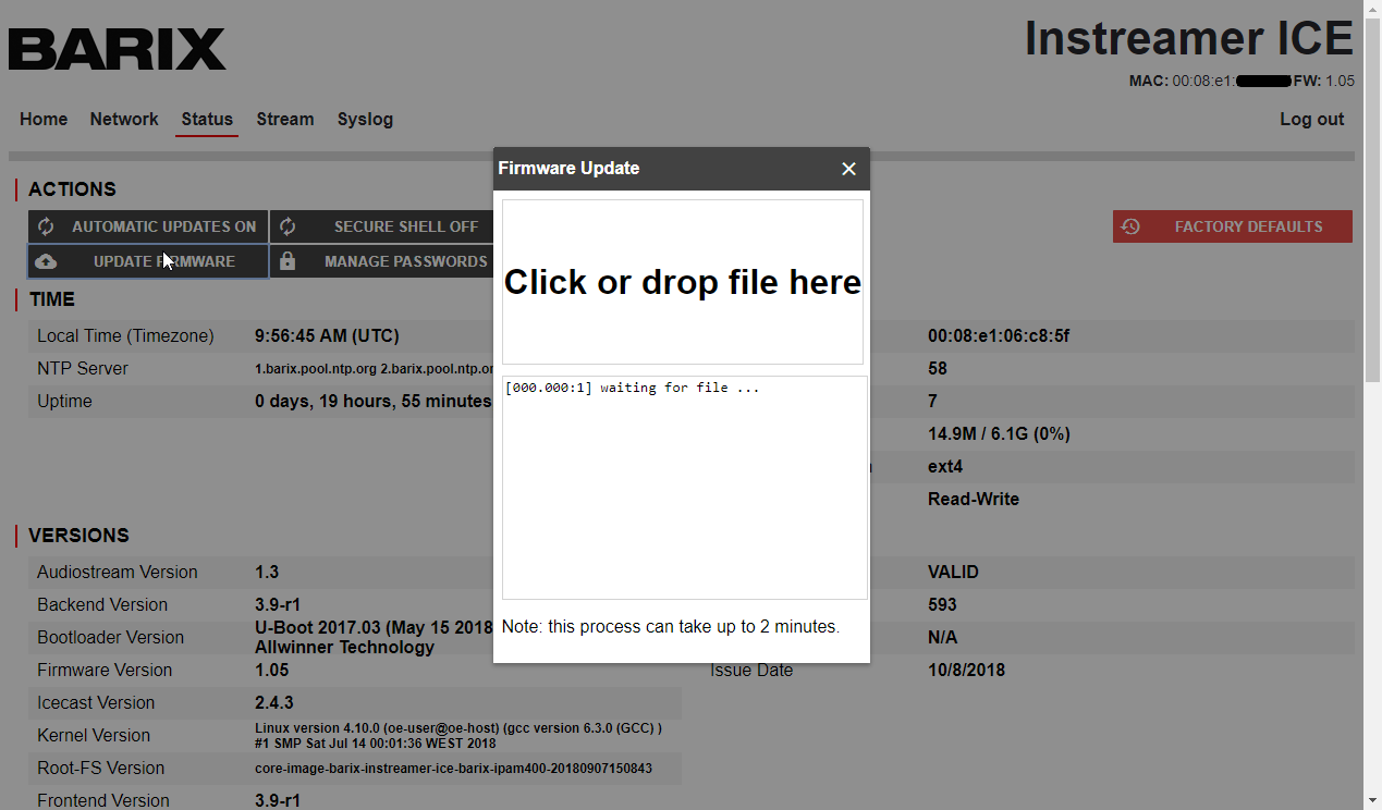
Illustration 11: Manual firmware upload process
By clicking the “UPDATE FIRMWARE” the Firmware Update window will open. Clicking “Click or drop file here” allows to select the Firmware file (.tar file archive). The Update process needs approximately 2 minutes and should be not interrupted, please wait until it is 100% completed before closing this window.
Note
Only “.tar” files can be selected for the firmware update, make sure you have downloaded the right file from the Barix homepage!
Warning
Don´t interrupt a running firmware update process! An uncompleted firmware update can result in a device not working properly.
Appendix A Specifications & Warranty
Instreamer ICE Specifications
Network Interface
RJ-45 10/100 Mbit auto-detect Ethernet interface
Protocols supported: TCP/IP, HTTP, HTTPS, ICMP, DHCP
Audio Interface
Stereo RCA connectors (Cinch connectors)
Headphone Output
Female jack 3,5 mm (for Sonic IP address announcement only).
The encoded audio is not audible over this headphone interface !
LED Status
Two LEDs with red/green/orange
EXT.
Double connector type A to connect USB devices (currently not supported)
RS-232 Interface
DB-9 DTE interface
Audio Formats
MP3, AAC+
Power Supply Input
External power adapter 100-240VAC
Male connector: 5,5 * 2,1 mm
Physical Dimensions and Case
Alloy
108mm x 38 mm x 78,7mm (4,25 * 1,5 * 3,1 inch)
250g
Operating Temperature & Humidity
0 - 50º C (32 - 122º F)
0 – 70% relative humidity, no condensing
Warranty
two years
Certifications
CE, ROHS, others in examination
Instreamer ICE Warranty
The warranty terms are part of the General Terms and Conditions of Barix AG. The warranty period for defects due to material flaws, design errors or careless work is two years from time of purchase by the end customer. The contractual partner undertakes to notify supplier immediately in writing of any hidden defects identified during the warranty period.
The warranty does not apply for defects for which the supplier is not responsible, such as natural wear and tear, force majeure, handling and usage of the delivered product by the contractual partner or third parties which is inappropriate and contrary to regulations and purpose, interventions by the contractual partner or third parties, excessive loads, unsuitable equipment, faulty maintenance or extreme environmental influences, as well as in the event of modifications made by the contractual partner to products before reselling them to third parties.
The warranty also does not apply in the event of defects which would have been identified during the course of a proper inspection of the products, as specified in the General Terms and Conditions of Barix. The supplier undertakes at his discretion to repair as quickly as possible, or replace products which are demonstrably defective, during the warranty period as a result of the use of bad-quality materials, faulty design or poor workmanship or which do not exhibit the features contractually guaranteed. The contractual partner must provide the supplier with all relevant information for this. Replaced parts are the property of the supplier. If it transpires that the supplier is not responsible for a particular defect, the product shall be repaired by the supplier against payment.
The supplier is only ever liable for direct damage to the delivered item which has occurred at the contractual partner’s site. Liability for indirect or consequential damage, such as loss of profits, third party claims and damage caused by the contractual partner’s failure to comply with contractual obligations, is explicitly excluded.
The contractual partner does not have any further rights arising out of product defects other than those explicitly mentioned above.
RMA
If a device is deemed defective, the following procedure shall apply:
a) Customer claiming for defective device shall send a failure report to the distributor
b) Distributor shall review the failure report and provide any tips or suggest rectification measures
c) After investigation, distributor may authorize the customer for returning material (distributor RMA)
d) Any product found to be defective within 30 days of receipt at the customer shall be deemed Dead on Arrival (DOA) and advance replaced by the distributor.
e) Upon receipt of the failed device, the distributor shall attempt to operate a serial rescue with standard firmware, confirm failure and eventually attempt to determine the cause.
f) If failure is confirmed, the distributor shall contact Barix support (support@barix.com) providing the failure report in accordance with (a) and (e) and all relevant information.
g) Barix support reviews the failure report and provides tips or suggests rectification measures
h) After verification Barix support may authorize the distributor for returning material (Barix-RMA). For Barix-RMA products, returns to Barix are regarded as the provision of the products at the supplier's office.
i) In the event the defect is confirmed to have been caused by user mishandling (non-intended operation, incorrect connection, etc.), the device shall be repaired on a cost basis
j) For devices demonstrably defective during the warranty period, Barix shall authorize replacement of the defective device free of charge with the next regular shipment. Replaced parts are the property of the supplier.
k) If it transpires the supplier is not responsible for a particular defect, the product shall be repaired by the supplier against payment.
Appendix B IP Addresses, Netmasks and Gateways
Communication between devices on a network running the Internet Protocol (often abbreviated IP) is based each device on the network having a unique IP address. An IP address is a 32-bit value divided into four "octets" of eight bits each. The 32-bit IP address is commonly written with each of the four octets written as decimal numbers separated by dots[1].
For example: 192.168.0.40
One of the important features of the Internet protocol addressing scheme is its ability to divide a network into "subnets" that share some portion of the 32-bit IP address for all devices on the subnet. For example, all the devices on a small office or home network, often share the same first three octets in their IP addresses. Only the last octet is different for each device on such a network. Thus, all the devices on this type of network might have 192.168.0.xx as the first three octets and then each individual computer or device on the network has a unique last octet. For example, a particular computer on this subnet might have the IP address 192.168.0.40.
The part of the IP address that is common to all the devices on a particular subnet is called the "network prefix", since that part of the address defines a unique subnet. The part of the IP address that is unique to each individual device on the network is called the "host part".
In our first example, 192.168.0. is the "network prefix" while 40 is the "host part".
This scheme of dividing a network into subnets makes managing network traffic between devices on a network much more efficient, since much of the traffic between computers and other devices occurs within a subnet and does not affect devices on other subnets.
B.1 The Netmask Parameter
Every device on an IP network has a "netmask" parameter in addition to an IP address. The netmask defines which portion of the IP address is a "network prefix" and which portion is a "host part". Netmasks are written in the same notation (four octets separated by dots) as IP addresses.
Zeros in a netmask value represent portions of the IP address that are the host part, while 1's in the netmask (expressed in binary notation) represent portions of the IP address that are the network prefix.
In our example, the netmask for a subnet where all the devices share the first three octets would be 255.255.255.0. The first three values are all 1's in binary, so the first three octets are the network prefix. The last octet is zero, so all the bits of the last octet are the host part.
The following table shows several valid netmasks and the size (in bits) of the network address portion and the host address portion of the IP address.
Netmask | Network Prefix Bits | Host Part Bits | Maximum Number of Devices in the Subnet[2] |
|---|---|---|---|
255.255.255.252 | 30 | 2 | 2 |
255.255.255.248 | 29 | 3 | 6 |
255.255.255.240 | 28 | 4 | 14 |
255.255.255.224 | 27 | 5 | 30 |
255.255.255.192 | 26 | 6 | 62 |
255.255.255.128 | 25 | 7 | 126 |
255.255.255.0 | 24 | 8 | 253 |
255.255.254.0 | 23 | 9 | 510 |
255.255.252.0 | 22 | 10 | 1022 |
255.255.248.0 | 21 | 11 | 2046 |
… | … | … | … |
255.128.0.0 | 9 | 23 | 8,388,606 |
255.0.0.0 | 8 | 24 | 16,777,214 |
[1] This appendix describes IPv4 addresses which are the most common on the Internet. A newer IPv6 standard, using 128 bit addresses, instead of 32-bit addresses has been defined and is gradually supplanting the IPv4 scheme. However, most devices still implement IPv4 and most computers running modern operating system versions support both. This appendix does not address IPv6. The Instreamer ICE only supports currently IPv4.
[2] Keep in mind that two of the host addresses in the range (all zeros and all ones) are not valid for assignment to devices, so the maximum number of hosts is actually two less than the number of host addresses in the host address range. The next section discusses these special IP addresses that are not available for assignment to a device.
B.2 The Gateway Parameter
Whenever a device is attempting to make a connection to another device on the network, the device compares the address of the remote device to its own netmask and IP address. If the remote device's IP address is in the same subnet (i.e. it shares the same network address), a direct connection to the remote device can be made.
Going back to our example, assume that the Instreamer ICE has an IP address of 192.168.0.40 and a netmask of 255.255.255.0. For the sake of this example, assume that the Instreamer ICE wants to send a stream to a device at 192.168.0.32. Since this device is on the same subnet, (it shares the 192.10.0 portion of the IP address) the stream can be sent directly to the device at 192.10.0.32.
If, however, the stream is going to a device at 192.10.12.15, the remote device is not in the same subnet (remember, all devices in the Instreamer ICE´s subnet share the same first three octets, because the netmask is 255.255.255.0). When the remote device is not in the same subnet, the Instreamer ICE must communicate through the "gateway", which is a device that routes traffic between two subnets. Thus, the Instreamer ICE contacts the gateway and asks it to send the stream to the remote IP address. The gateway handles the routing required to deliver the message to the remote subnet.
The gateway parameter specifies the IP address of the gateway that routes traffic to another subnet. The gateway IP address must always be in the same subnet as the device. The gateway device actually has at least two IP addresses—one on the local subnet, and one on the other subnet(s) it routes to).
If you are statically assigning an IP address to the Instreamer ICE, and it will need to connect to other computers or devices outside its own subnet, you must fill in the gateway IP address. If the Instreamer ICE is not communicating with any devices outside its own subnet, you can leave the gateway parameter blank.
If the Instreamer ICE is obtaining its IP address automatically from a DHCP server, the DHCP server will assign the IP address and netmask, and may also supply the gateway address.
B.3 Special IP Addresses
Some ranges of IP addresses have special meaning, and therefore aren't available for assignment to a device on the subnet.
An IP address with a host address portion of all 1's implies a "broadcast" to all devices on the subnet. If the Instreamer ICE has an IP address of 192.10.0.40 and a netmask of 255.255.255.0, the broadcast address for this subnet is 192.10.0.255. No device on the network, including the Instreamer ICE can have an IP address of 192.10.0.255.
The address 127.0.0.1 is also a special address that is called a "loopback" address. This is not a valid address to assign to the Barionet.
B.4 Private IP addresses and the Internet
Because of the limited range of IP addresses in the most common version of the Internet protocol5, a series of "private" IP address ranges have been defined that allow any number of private networks to use the same range of IP addresses. These "private" IP ranges are translated to one or more "public" IP addresses for access to the internet using a protocol called "Network Address Translation" or NAT. Most modern routers used in small home or office networks implement NAT so that a single public IP address can be shared by an entire network of computers using a range of these private IP addresses.
The same principles apply to the assignment IP address, netmask, and gateway IP address in a private network. The primary difference is that private network IP addresses don't have to be unique across the entire internet, while public IP addresses must be unique.
If the network you're connecting your Instreamer ICE to is not connected to the internet, you can choose any address range you like. However, if the network is, or will be connected to the internet in the future, it's wise to use one of the private IP address ranges and a NAT-capable router/firewall for connecting to the Internet. If you have questions about these networks, and the appropriate address to assign to an Instreamer ICE, contact your network administrator.
The table below shows the range of private IP addresses defined for each of the three "classes" of private networks.
Class | IP Addresses | Netmask | Max number of devices |
|---|---|---|---|
A | 10.x.x.x | 255.0.0.0 | 16,777,214 |
B | 172.16.x.x | 255.255.0.0 | 65,534 |
C | 192.168.0.x | 255.255.255.0 | 254 |
Acceptance Reviews and Approvals
Name | Changes | Review Date |
|---|---|---|
Jerome Castan | 03.08.2018 | |
Stefan Giessler | 10.08.2018 | |
Jerome Castan |
| 19.09.2018 |
Jerome Castan |
| 21.09.2018 |
Jerome Castan |
| 26.03.2019 |
Giacomo Trovato/Stefan Giessler |
| 27.08.2019 |
Stefan Giessler |
| 16.09.2021 |
Stefan Giessler |
| 07.12.2021 |
Stefan Giessler |
| 10.01.2023 |
Compliance and further Information
This equipment has been tested and found to comply with the limits for a Class B digital device, pursuant to part 15 of the FCC Rules. These limits are designed to provide reasonable protection against harmful interference in a residential installation. This equipment generates, uses and can radiate radio frequency energy and, if not installed and used in accordance with the instructions, may cause harmful interference to radio communications. However, there is no guarantee that interference will not occur in a particular installation. If this equipment does cause harmful interference to radio or television reception, which can be determined by turning the equipment off and on, the user is encouraged to try to correct the interference by one or more of the following measures:
Reorient or relocate the receiving antenna.
Increase the separation between the equipment and receiver.
Connect the device into an outlet on a circuit different from that to which the receiver is connected.
Consult the dealer or an experienced radio/TV technician for help.
Safety and precaution recommendations apply. Find them in the download section at www.barix.com

Find your distributor on this list for more hardware.
For questions that are extending the documentation, feel free to contact us on:
International: +41 434 33 22 22
USA: +1 866 815 0866
Email: support@barix.com
All information and the use of this product including all services are covered under the Barix Terms & Conditions and our Privacy Policy. Please follow the Safety and Precaution Recommendations. Barix is a ISO 9001:2015 certified company. All rights reserved. All information is subject to change without notice. All mentioned trademarks belong to their respective owners and are used for reference only.